Active infrared sensor

a technology of infrared sensor and infrared sensor, which is applied in the direction of photometry using electric radiation detectors, optical radiation measurement, instruments, etc., can solve the problems of increasing the likelihood of occurrence of undetected intrusion events, preventing satisfactory detection, and undetected intrusion events, so as to inhibit the increase of infrared sensor costs

Inactive Publication Date: 2005-07-19
OPTEX CO LTD
View PDF5 Cites 19 Cited by
  • Summary
  • Abstract
  • Description
  • Claims
  • Application Information

AI Technical Summary

Benefits of technology

[0014]As a result of such specific features, by choosing large ratio(s) of infrared pulse OFF time(s) relative to ON time(s), it is possible to attain small value(s) of integrated optical energy that is transmitted during infrared output period(s) and low optical output in the infrared signal(s) transmitted from optical transmitter means. Conversely, by choosing mall ratio(s) of infrared pulse OFF time(s) relative to ON time(s), it is possible to attain large value(s) of integrated optical energy that is transmitted during infrared output period(s) and high optical output in infrared signal(s) transmitted from the optical transmitter means. That is, this makes it possible for the transmitted optical output to be made variable through the adjustment of ratio(s) between infrared pulse ON time(s) and OFF time(s), which is something that can be implemented through software control alone; and makes it possible to carry out a multileveled adjustment of the transmitted optical output without the need for complicated electrical circuitry, which is something that would involve hardware design.
[0019]The use of these techniques either individually or in mutual combination makes it possible to switch among multiple levels of the transmitted optical output.
[0023]Such techniques make it possible to cause infrared pulses outputted during infrared output period(s) to be output in accordance with the selected or generated optical transmission pattern(s), as a result of which the optical output of the infrared signal(s) transmitted from the optical transmitter means is made variable. In particular, where infrared pulses are output at frequency or frequencies and with ON time duration(s) as determined by the respective aforementioned sending circuits, there is no need to prepare and store a plurality of optical transmission patterns in advance, thereby permitting reductions to be achieved in the required storage capacity and making it possible to inhibit increases in infrared sensor cost.
[0024]Furthermore, if at least one of the optical transmitter means and / or at least one of the optical receiver means is / are provided with at least one activation means for activating at least one functionality by means of which at least one of the transmitted pulse modulation means varies transmitted optical output, it will be possible to cause varying of optical output of transmitted infrared signal(s) to be carried out automatically. This means that there will no longer be a need for a user to perform operations for varying transmitted optical output in correspondence to the environment and / or the conditions under which the infrared sensor is used.
[0025]Furthermore, it will also be possible to cause varying of the optical output of transmitted infrared signal(s) to be carried out automatically if at least one of the optical receiver means is provided with at least one request sending means which is capable of sending to at least one of the optical transmitter means at least one request signal for requesting action of at least one functionality by means of which at least one of the transmitted pulse modulation means varies the transmitted optical output.

Problems solved by technology

However, changes in environment and / or conditions under which they are used may cause the optical receiver elements of such infrared sensors to become saturated, thereby preventing satisfactory detection.
As a result, despite the fact that an intruder or the like may have passed between an optical transmitter and an optical receiver, interrupting the infrared beam therebetween, because this feedback beam irradiates the optical receiver, the optical receiver is unable to detect an interruption of the infrared beam by the intruder or the like, which results in an undetected intrusion event.
Particularly where water has collected on the ground as a result of rainfall or snow has accumulated as a result of snowfall, there is a tendency for the intensity of this feedback beam to become large, thereby increasing the likelihood of occurrence of an undetected intrusion event.
However, because the means for making transmitted optical output variable which is disclosed in the foregoing publication requires complicated electrical circuitry, in practice, it is only actually possible to switch between on the order of two levels of transmitted optical output.
Moreover, with a device such as this, which only permits switching between on the order of two levels, depending on the environment and / or the conditions under which the infrared sensor is used, it may not be possible to completely eliminate the aforementioned shortcomings which are caused by the feedback beam.
While a constitution that would permit switching among multiple levels of transmitted optical output has therefore been desired, a practical solution has been difficult because of the concomitant increased complexity in electrical circuitry which would result therefrom as described above.

Method used


Image

  • Active infrared sensor
  • Active infrared sensor
  • Active infrared sensor

Examples


first embodiment

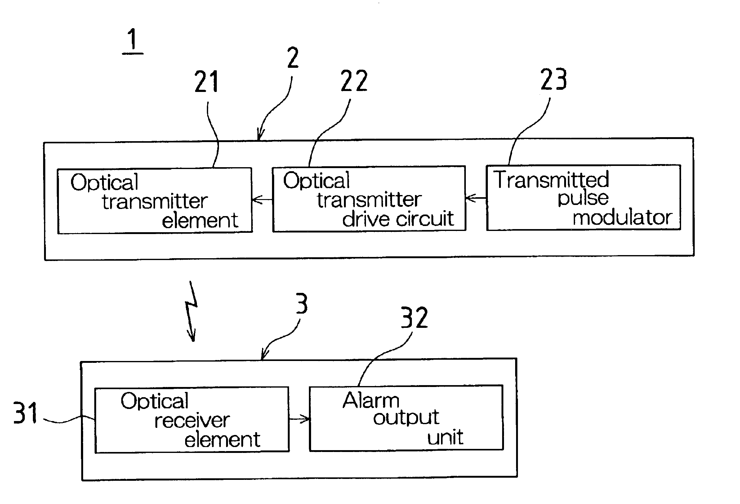
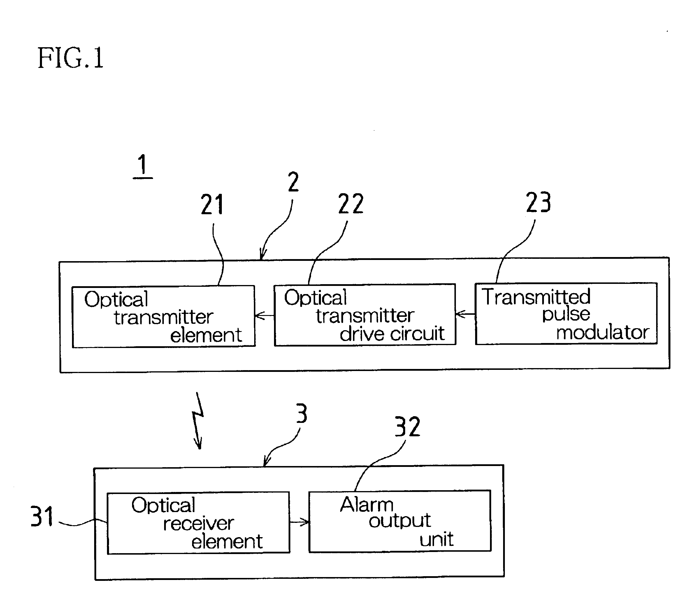
[0038]A first embodiment of the present invention will now be described. FIG. 1 is a block diagram showing the constitution of an active infrared sensor 1 according to the first embodiment of the present embodiment. Such an active infrared sensor 1 might be installed at a prescribed protected area, and might output an alarm to a system control panel (not shown) which activates a security camera (not shown) or which contacts a security company when the entry of a person into such protected area is detected.

[0039]As shown in FIG. 1, the active infrared sensor 1 is such that optical transmitter(s) 2 serving as optical transmitter means and optical receiver(s) 3 serving as optical receiver means are arranged in protected area(s) in opposing fashion with prescribed distance(s) therebetween along an optical axis or axes traveled by infrared pulses which are transmitted by the optical transmitter(s) 2 and described below.

[0040]Such an optical transmitter 2 is equipped with optical transmit...

second embodiment

[0056]A second embodiment of the present invention will now be described. In the infrared sensor of the foregoing first embodiment, the respective optical transmission patterns were stored in advance at transmitted pulse modulator 23. In the second embodiment, desired optical transmission pattern(s) is / are generated at the transmitted pulse modulator 23. As the constitution of the second embodiment is in other respects similar to that of the first embodiment, the description here of the second embodiment will be confined to that structure which is responsible for the generation of the optical transmission pattern(s).

[0057]As shown in FIG. 9, the transmitted pulse modulator 23 of the second embodiment is equipped with first and second sending circuits 23A, 23B. The first sending circuit 23A is a circuit for determining the frequency or frequencies of infrared pulses which are output during infrared output period(s). The second sending circuit 23B is a circuit for determining the dura...

third embodiment

[0062]A third embodiment of the present invention will now be described. The third embodiment relates to a constitution for causing the optical output of the transmitted infrared signal(s) to be varied automatically. As the constitution of the third embodiment is in other respects similar to that of the foregoing first embodiment, the description here of the third embodiment will be confined to that structure which is responsible for causing the transmitted optical output to be varied automatically.

[0063]As shown in FIG. 10, the optical transmitter 2 of the third embodiment is provided with activation circuit(s) 24 serving as activation means for activating the ability of the transmitted pulse modulator(s) 23 to vary the transmitted optical output. Optical transmission pattern(s) selected as described above is / are again selected through the action of this activation circuit 24 in correspondence to the environmental conditions and / or the conditions under which infrared sensor 1 is us...


PUM


Abstract

An optical transmitter is equipped with a transmitted pulse modulator at which a plurality of optical transmission patterns have previously been stored. The respective stored optical transmission patterns have mutually different ratios between infrared pulse ON times and OFF times. The optical output of infrared signal(s) transmitted from an optical transmitter is made variable as a result of the fact that infrared pulse(s) output during infrared output period(s) is / are output in accordance with an optical transmission pattern which is selected from among the plurality of optical transmission patterns.

Description

BACKGROUND OF THE INVENTION[0001]1. Field of the Invention[0002]The present invention relates to an active infrared sensor which may be used in security systems and the like. In particular, the present invention pertains to an improvement for making variable the transmitted optical output from an optical transmitter means.[0003]2. Description of the Related Art[0004]As disclosed, for example, in Japanese Patent Application Publication Kokai No. H13-188970 (2001), applications in which active infrared sensors are used in security systems to detect the entry of persons into protected areas are conventionally known. Such sensors are typically equipped with optical transmitters employing internal optical transmitter elements, and optical receivers employing internal optical receiver elements. Such optical transmitter(s) and optical receiver(s) might be arranged in opposing fashion so as to straddle a protected area such that infrared beam(s) from the optical transmitter(s) is / are transm...

Claims


Application Information

Patent Timeline
Patent Type & Authority Patents(United States)
IPC IPC(8): G08B13/183G08B13/18G01V8/12G01J1/42H01L31/12
CPCG08B13/183
Inventor IWASAWA, MASASHI
Owner OPTEX CO LTD
Why Eureka
Try Eureka