

Glass funnel for a cathode ray tube and cathode ray tube
a glass funnel and cathode ray tube technology, which is applied in the direction of cathode ray tubes/electron beam tubes, electric discharge tubes, electrical apparatus, etc., can solve the problems of unstable deformation inability to display images, and fracturing of cathode ray tubes, so as to reduce tensile stresses and reduce weight , the effect of high degree of freedom in design
Inactive Publication Date: 2005-07-19
ASAHI GLASS CO LTD
View PDF20 Cites 2 Cited by
- Summary
- Abstract
- Description
- Claims
- Application Information
AI Technical Summary
Benefits of technology
The present invention provides a glass funnel for a cathode ray tube with a bent portion to control the transmission of deformation energy from the body portion to the yoke portion, thus decreasing a tensile stress in the yoke portion and preventing it from being fractured. The bent portion can be positioned at a specific position of the body portion and can have different shapes, such as a projected portion or a stepped portion, with a specific size. The use of the glass funnel can improve the performance and reliability of cathode ray tubes.
Problems solved by technology
When the glass is cracked forming the cathode ray tube in such a state, the crack will extend to release the high deformation energy inherent in the cathode ray tube, finally fracturing the cathode ray tube in some cases.
Further, in such a condition that a high stress is applied to an outer surface of the cathode ray tube, delayed fracture (fracture caused after lapse of a period of time) may occur due to the action of moisture in the atmosphere, making it impossible to display an image, in some cases.
In comparison with display devices other than cathode ray tubes, it is pointed out that the display devices comprising a cathode ray tube have a main disadvantage of having a long depth.
An increase in the tensile stresses brings about a decrease in reliability because of a reduction in safety by fracture or because of delayed fracture.
When the glass thickness of the yoke portion is increased, the yoke portion necessarily needs to project inwardly in order to mount a deflection coil on the outer side thereof, causing, e.g., a serious problem that electron beams impinge on an inner surface of the yoke portion to significantly degrade image quality.
Method used
View moreImage
Smart ImageViewing Examples


Examples
example 1
[0072]A glass funnel having a projected portion provided around the entire periphery of the outer peripheral area as shown in FIG. 3.
example 2
[0073]A glass funnel similar to Example 1 except that the thickness of the projected portion and the thickness of the body portion were set as listed in Table 2.
example 3
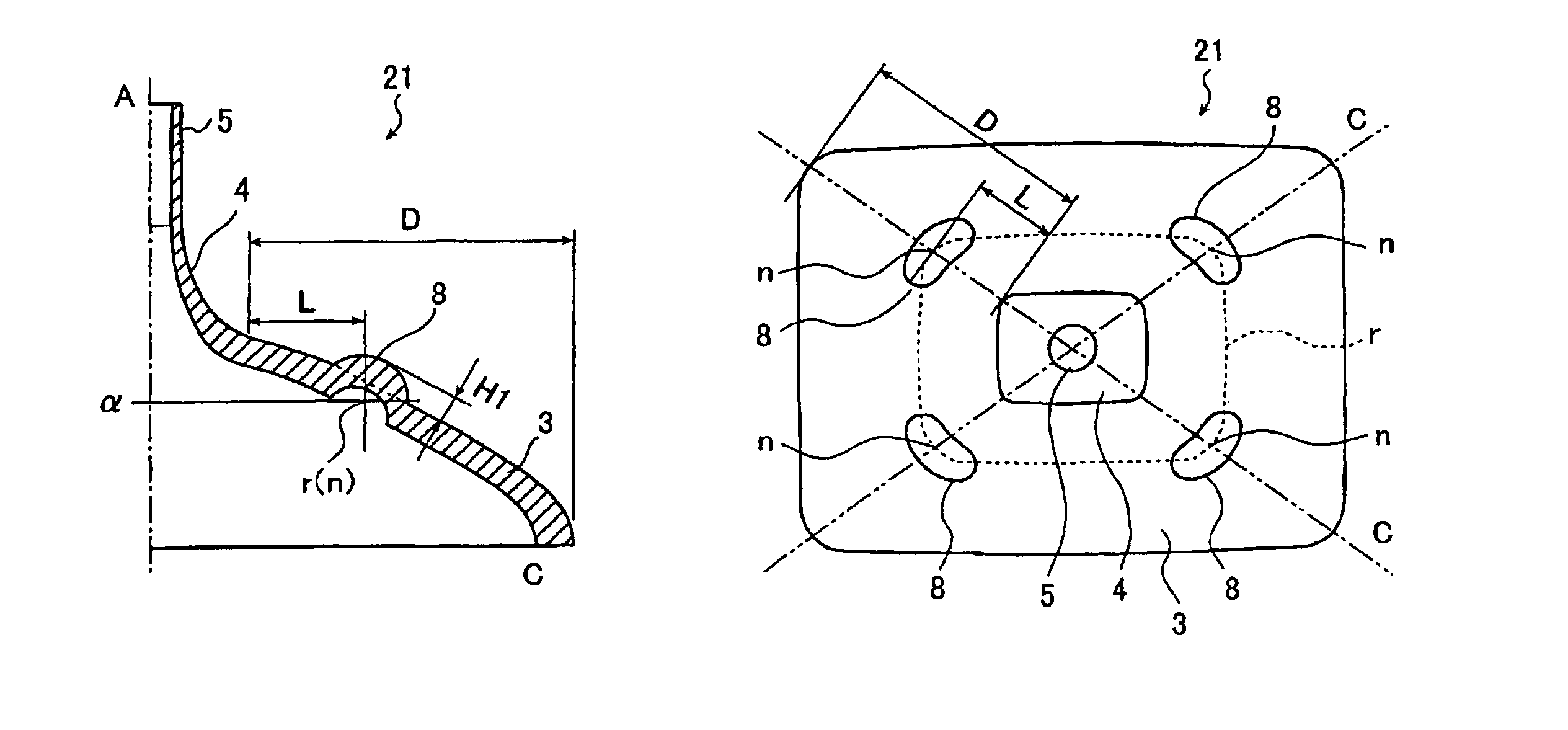
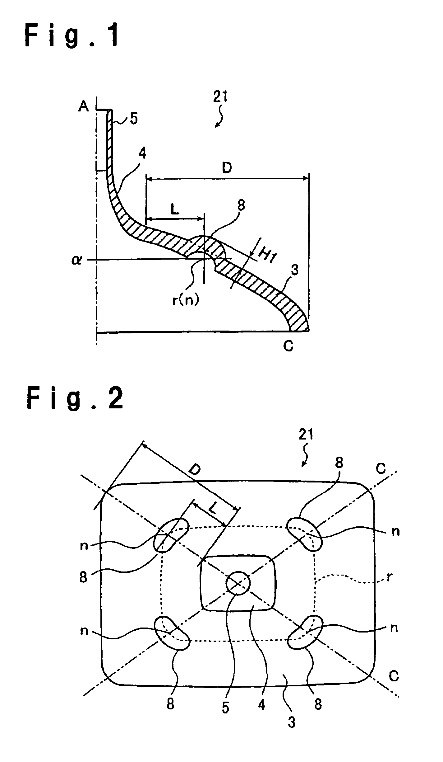
[0074]A glass funnel having a projected portion discontinuously provided around the outer peripheral area as shown in FIG. 1 and FIG. 2.
Login to View More PUM
 Abstract
The present invention has an object to provide a glass funnel, which is safe, highly reliable and lightweight. The object is solved by a glass funnel wherein an outwardly projecting bent portion is provided along at least a part of an outer peripheral area, where the body portion intersects with a plane perpendicular to a bulb axis, and which includes intersecting points between the outer peripheral area and a plane containing a diagonal axis and the bulb axis, and the bent portion is provided at a specific position.
Description
[0001]This is a continuation of application Ser. No. PCT / JP02 / 10802, filed Oct. 17, 2002.TECHNICAL FIELD[0002]The present invention relates to a glass funnel for a cathode ray tube, which is mainly used in a TV broadcast receiver or an image display device for industrial use.BACKGROUND ART[0003]As shown in FIG. 9, a cathode ray tube 20 is basically composed of a glass panel for displaying an image 1, and a glass bulb including a glass funnel 2 having a neck portion 5 for housing an electron gun 6.[0004]Referring to FIG. 9, the glass funnel 2 includes a body portion 3 having an open end for connection with the glass panel 1, the neck portion 5 for housing the electron gun 6, and an yoke portion connecting between the body portion and the neck portion and having an outer side configured so as to mount a deflection coil (deflection yoke) as a deflection unit for deflecting electron beams irradiated from the electron gun thereon. In FIG. 9, reference numeral 10 designates a sealing port...
Claims
Login to View More Application Information
Patent Timeline
 Patent Type & AuthorityPatents(United States)
IPC IPC(8): H01J29/86
CPCH01J29/861H01J2229/8606H01J29/86
InventorMURAKAMI, TOSHIHIDE
OwnerASAHI GLASS CO LTD