Systems and methods for passivation of servo motors

a technology of servo motors and passivation, applied in the direction of electric controllers, instruments, ignition automatic control, etc., can solve the problems of inconvenient operation of motors, inconvenient movement, and inability to passivate servo motors

Inactive Publication Date: 2005-07-19
MPC PRODS
View PDF7 Cites 11 Cited by
  • Summary
  • Abstract
  • Description
  • Claims
  • Application Information

AI Technical Summary

Benefits of technology

[0007]The passivation of servo motors is achieved by adding control systems providing plural independent control lanes in the operation of a conventional three-phase pulse width modulated (PWM) servo amplifier, providing that each control lane agrees on the magnitude of current in each phase. The PWM synchronization may be achieved with two independent PWM outputs from each of two channels, A and B Lanes, to control a three-phase power bridge for the DC motor. The PWM frame start is synchronized together by using a common start point, i.e., a clock that initiates the PWM cycle. Each independent control channel of A Lane and B Lane then uses motor rotor positiona

Problems solved by technology

Due to the need to use control electronics to control switching devices, a fault in the motor controller may cause incorrect motor operation, i.e., controller may cause incorrect motor operation, i.e., uncommanded motion.
A failure of a commutation position sensor

Method used


Image

  • Systems and methods for passivation of servo motors
  • Systems and methods for passivation of servo motors
  • Systems and methods for passivation of servo motors

Examples


Embodiment Construction

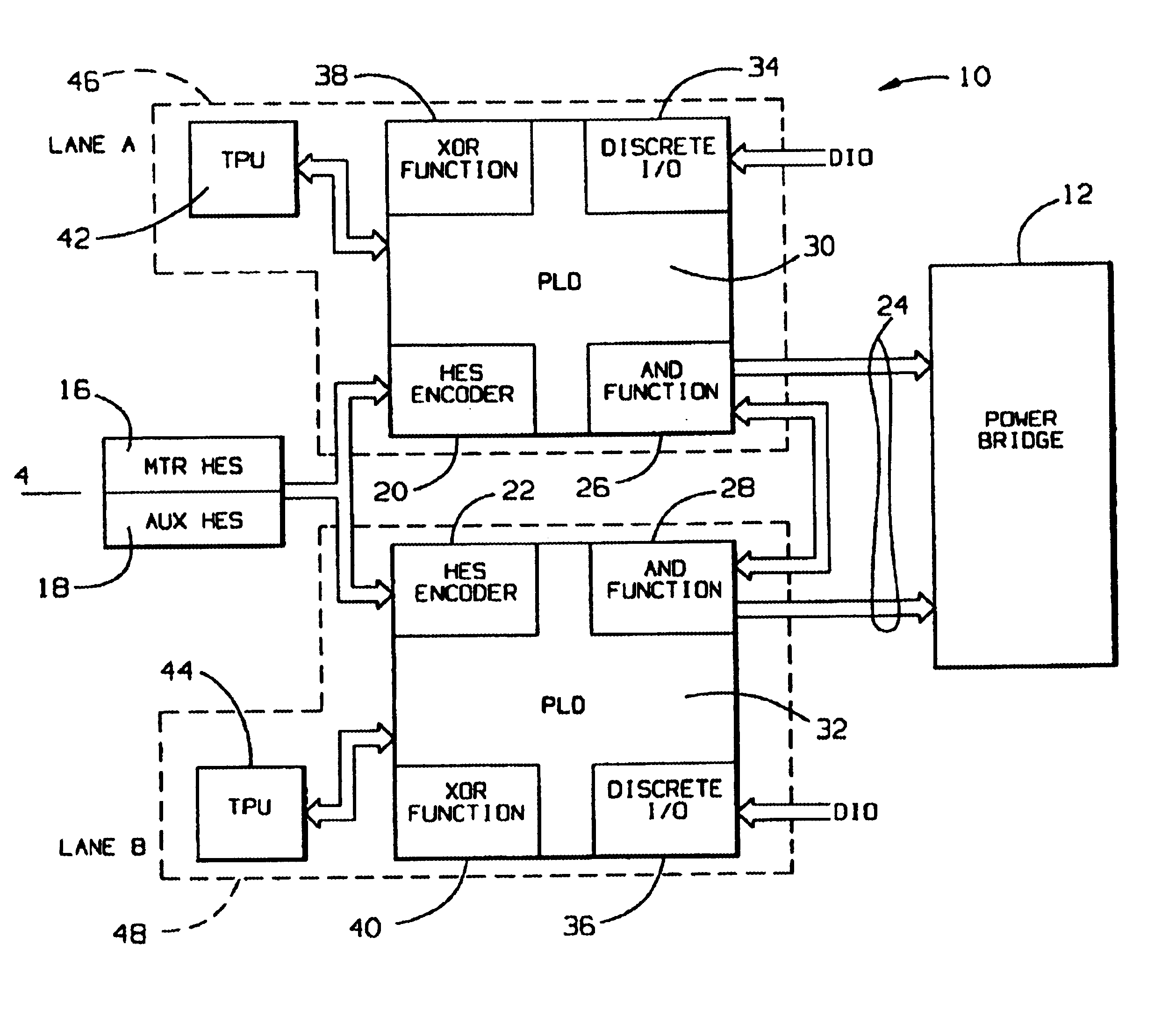
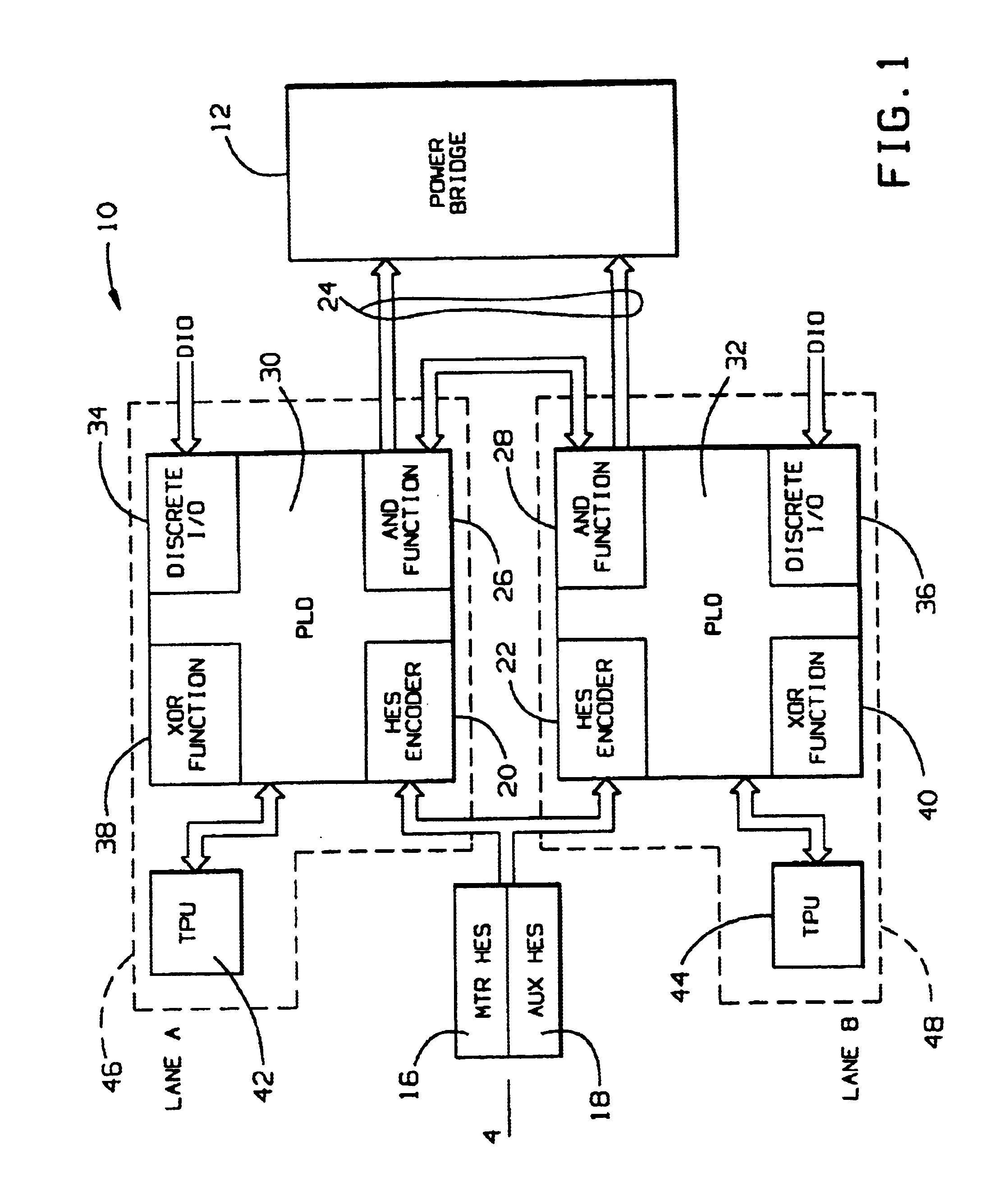
[0017]With reference to the drawings and particularly FIG. 1, which illustrates an embodiment for controlling brushless motors, the system generally indicated at 10 is provided for controlling a power bridge 12, employing the described systems and methods for passivation of servo motors. A sensor assembly 14 includes a motor Hall Effect Sensor (HES) 16 and an auxiliary HES 18 for generating signals indicative of the position of the motor rotor, which are provided to HES encoders 20 and 22 of respective Programmable Logic Devices (PLDs) 30 and 32 discussed below to provide position counter information from the sensor assembly 14 for the implementation of independent decision-making channel control paths to a PWM interface 24, which provides commutation signals to the power bridge 12. As further discussed below, the PWM interface 24 derives signals from logical AND functions 26 and 28 implemented with PLDs 30 and 32. The PLDs 30 and 32 also provide input / output functions with discrete...


PUM


Abstract

Servo motor controls are disclosed for passivation in the event of failures with at least two independent control paths and validation of positional information. A sensor assembly generates signals indicative of the position of the motor rotor, and a signal validation detector is used to validate the generated signals and inhibit rotation of the motor rotor when the sensor assembly generates an invalid signal. A first information processor is provided in communication with the sensor assembly for receiving the generated signals to establish an A Lane decision-making channel control path to the PWM interface, and a second information processor is in communication with the sensor assembly to establish a B Lane decision-making channel control path to the PWM interface. Control logic provided with a PWM interface also inhibits rotation of the motor rotor when a decision from the A Lane differs from a decision from the B Lane. The commutation signal detector provides a state machine to validate the commutation and ensure the validity of signals indicating the position of the motor rotor from the sensor assembly.

Description

BACKGROUND OF THE INVENTION[0001]1. Field of the Invention[0002]The present invention relates to systems and methods for controlling electric motors, and more particularly to controlling a power bridge for brushless, direct current (DC) motors for passivation of servos by inhibited motor rotor operation in the event of a failure.[0003]2. Description of Related Art[0004]In mission-critical applications, and in the aviation industry in particular, there is a need to have mechanical systems fail passively. To this end, motion devices such as electric motors are typically required to stop in their last pre-fault position in a locked state to prevent runaway or positional disturbances and the like in mechanical systems during failure.[0005]Three-phase, brushless, direct current (DC) motors employing conventional designs have been used extensively in servo controls for mechanical systems. A typical brushless servo motor includes a permanent magnet rotor and three-phase stator windings. Th...

Claims


Application Information

Patent Timeline
IPC IPC(8): G05B9/02
CPCG05B9/02
Inventor SZULYK, ZENON
Owner MPC PRODS
Why Eureka
Try Eureka