Capacitor coupled voltage transformer and its input voltage parameter determination

a coupled voltage transformer and input voltage technology, applied in the direction of instruments, base element modifications, measurement instrument braking, etc., can solve the problems of inability to accurately measure harmonic voltages and inability to achieve accurate measurements at ehv and uhv levels that require a wider bandwidth

Inactive Publication Date: 2005-07-19
GHASSEMI FOROOZAN
View PDF11 Cites 22 Cited by
  • Summary
  • Abstract
  • Description
  • Claims
  • Application Information

AI Technical Summary

Benefits of technology

[0006]It is an object of the present invention to enable one successfully t

Problems solved by technology

However, due to their construction, CVTs do not have a good frequency characteristic and are generally tuned to give an accurate picture of their primary voltage at a reduced voltage, usually 60 to 110 volts, for the fundamental frequency component only.
Accurate measurements at EHV and UHV levels that r

Method used


Image

  • Capacitor coupled voltage transformer and its input voltage parameter determination
  • Capacitor coupled voltage transformer and its input voltage parameter determination
  • Capacitor coupled voltage transformer and its input voltage parameter determination

Examples


Embodiment Construction

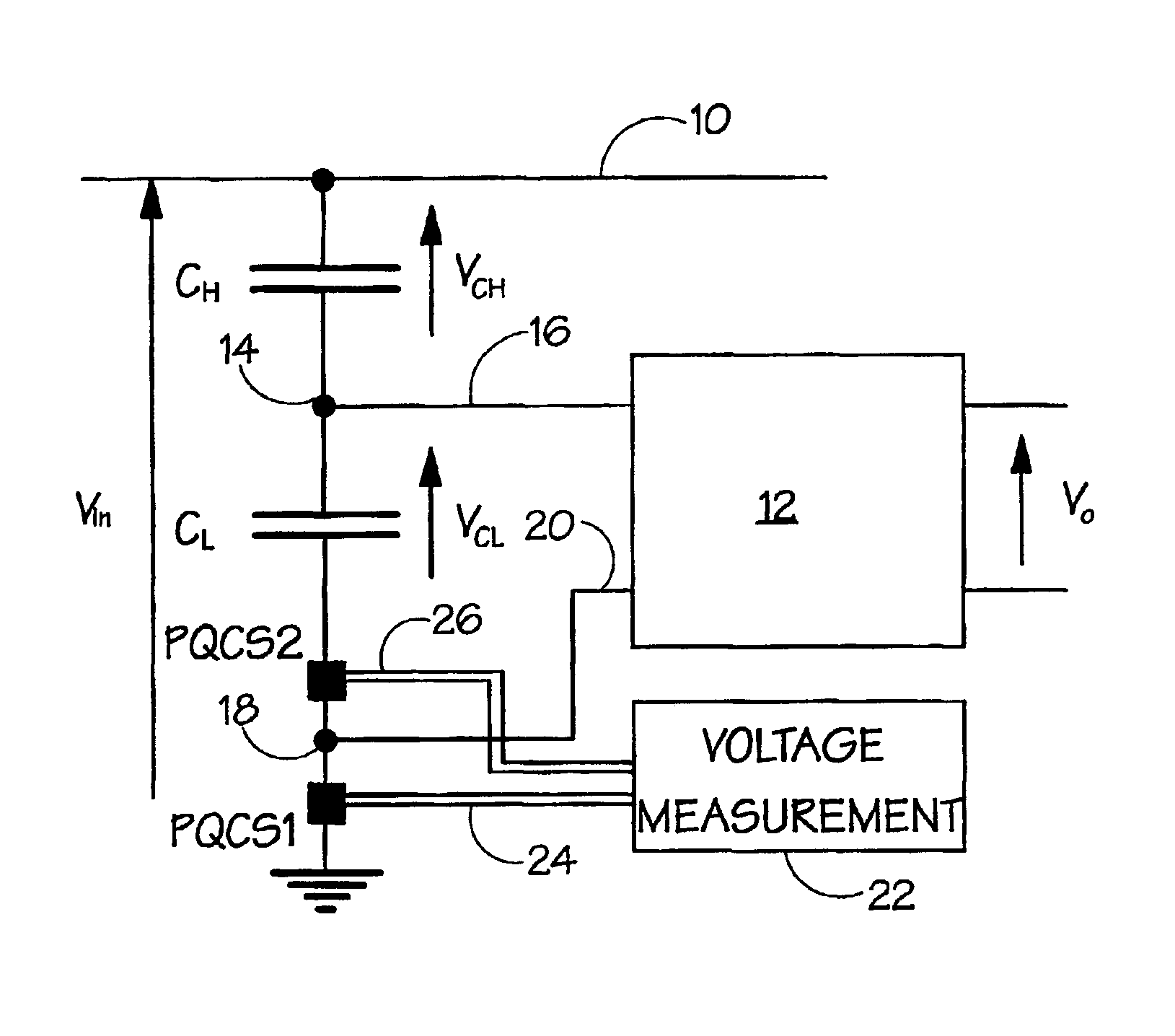
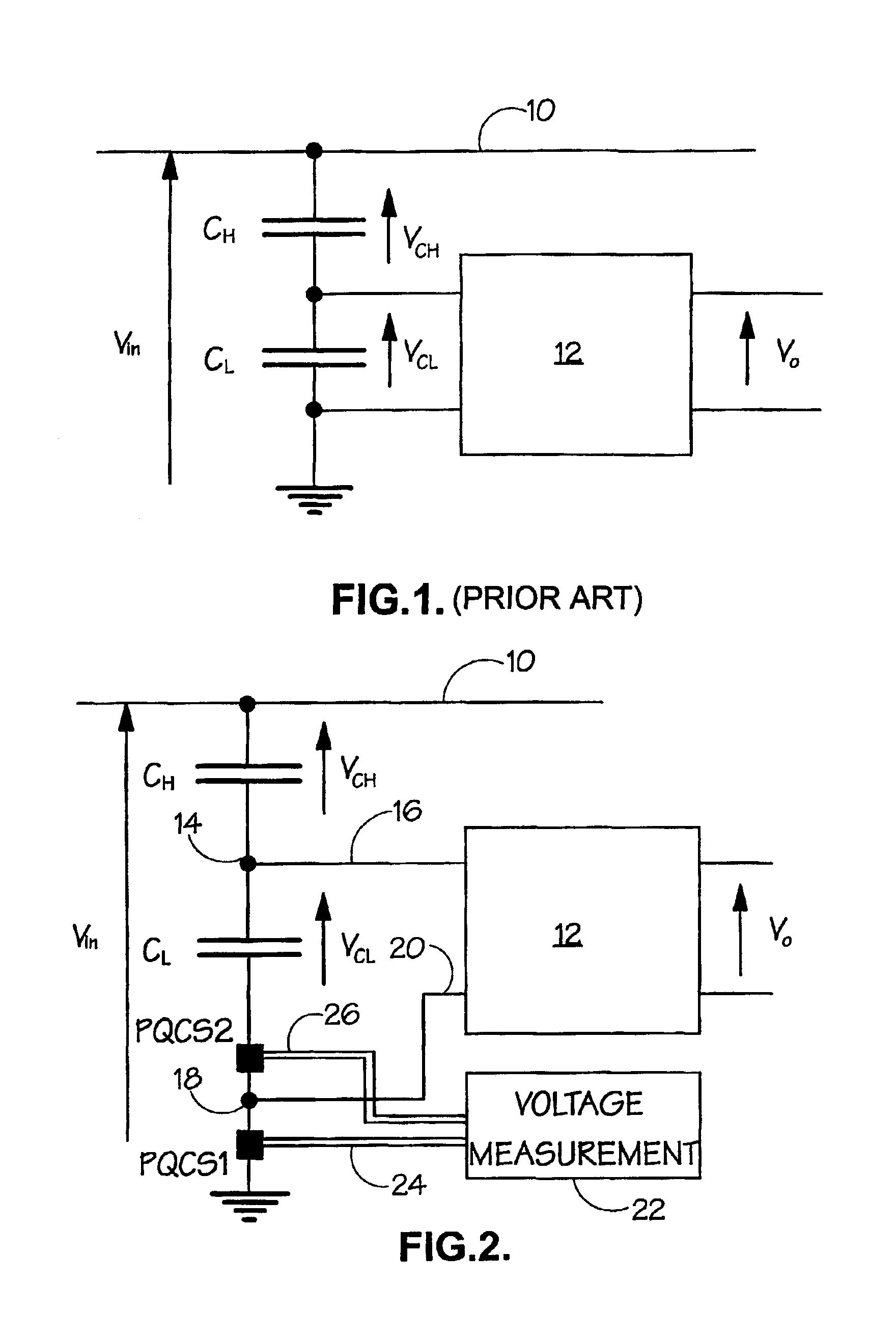
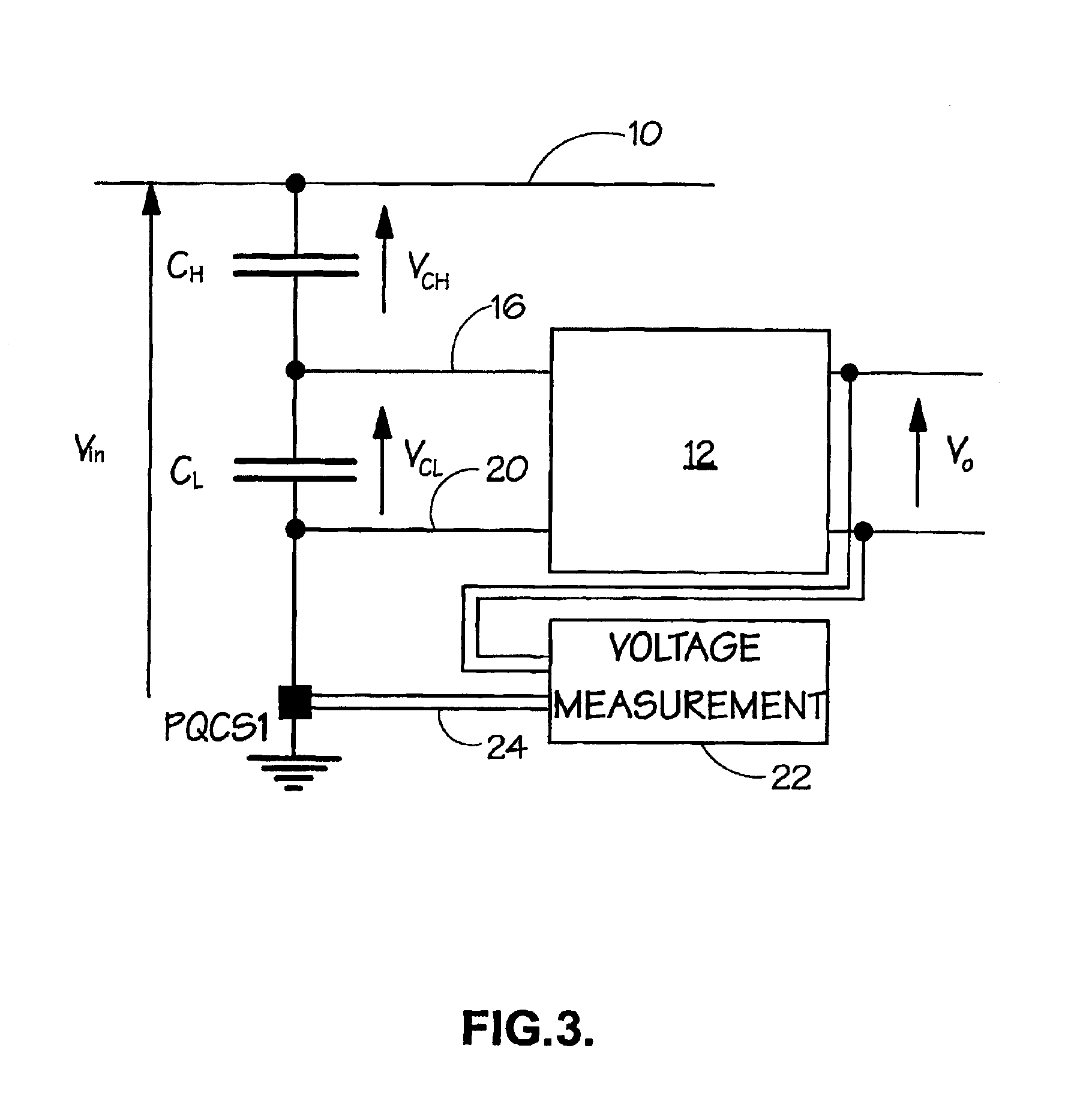
[0020]Before describing the embodiments in accordance with the invention, reference is first made to the prior art CVT shown in FIG. 1. CH and CL are high and low voltage capacitor banks respectively, connected in series between a rail 10 and earth. Connected across the low voltage capacitor bank CL are the other components of the CVT, usually a tuning reactor, a step-down transformer and a ferroresonance oscillation damping circuit. These components are indicated generally at 12. The input voltage to the CVT is indicated as Vin, and the output voltage as Vo. The voltage drop across the high voltage capacitor CH is indicated as VCH and the voltage drop across the low voltage capacitor CL is indicated as VCL.

[0021]The inherent characteristics of a CVT make it behave electrically as a filter, with the main bandpass accurately tuned to the fundamental frequency component. This in turn implies that the transformer output does not represent an accurate picture of the frequency contents o...


PUM


Abstract

Accurate harmonic measurements on electrical power systems where the main instrument transformers are of the capacitor coupled voltage type (CVT type) is made possible by the provision of one or more current sensors (PQCS1, PQCS2). CVTs typically have a high voltage capacitor bank (CH) and a low voltage capacitor bank (CL). One or more current sensors (PQCS1, PQCS2) is/are positioned so as to measure capacitor current and from that the input voltage (Vin) of the CVT can be determined for each frequency.

Description

FIELD OF THE INVENTION[0001]This invention relates generally to capacitor coupled voltage transformers, also known as capacitor voltage transformers or CVTs. These transformers are used inter alia as the main transformers for interfacing instrumentation, such as meters and protection devices, with extra high voltage (EHV) and ultra high voltage (UHV) systems.BACKGROUND TO THE INVENTION[0002]Capacitor voltage transformers are presently preferred to conventional electromagnetic type transformers because, in comparison, they are less expensive and are smaller in size.[0003]However, due to their construction, CVTs do not have a good frequency characteristic and are generally tuned to give an accurate picture of their primary voltage at a reduced voltage, usually 60 to 110 volts, for the fundamental frequency component only. Accurate measurements at EHV and UHV levels that require a wider bandwidth is not possible if the only instrument transformer present on the system is of the CVT typ...

Claims


Application Information

Patent Timeline
IPC IPC(8): G01R15/00G01R15/06G01R15/16G01R15/14
CPCG01R15/06G01R15/16
Inventor GHASSEMI, FOROOZAN
Owner GHASSEMI FOROOZAN
Why Eureka
Try Eureka