

Liquid crystal display device and electronic apparatus
a technology of electronic equipment and liquid crystal display device, which is applied in the direction of mirrors, instruments, telephone set constructions, etc., can solve the problems of difficult to obtain high-contrast images and bright images, difficult to view images in dark places, and high cost in tim
Inactive Publication Date: 2005-07-19
138 EAST LCD ADVANCEMENTS LTD
View PDF19 Cites 16 Cited by
- Summary
- Abstract
- Description
- Claims
- Application Information
AI Technical Summary
Benefits of technology
"The present invention relates to a liquid crystal display device with improved display quality. The device includes a reflective display region and a transmissive display region, and a thickness of the liquid crystal layer in the reflective display region is smaller than that in the transmissive display region. This allows for uniform retardation in both regions, resulting in brighter and higher-contrast images. The reflective display region includes a reflection layer and a transmissive scattering layer, and the transmissive display region includes a lower electrode, a liquid crystal layer, and an upper electrode. The device also includes a color filter in both regions, with different spectral characteristics to ensure higher contrast in the transmissive display mode. The transmissive scattering layer comprises a polymer matrix and a filler dispersed in the polymer matrix."
Problems solved by technology
However, since reflective liquid crystal display devices use outside light, such as natural light and illumination light, to display images, it is difficult to view the images in dark places.
This makes it difficult to obtain high-contrast images and bright images.
However, the formation of these asperities requires, for example, several applications of photolithography and, therefore, much expense in time.
Method used
View moreImage
Smart ImageViewing Examples

Examples
first embodiment
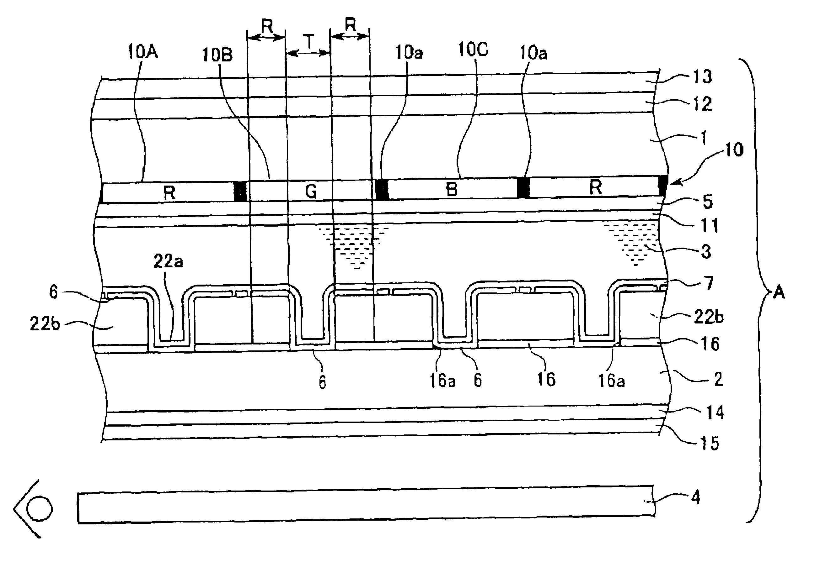
[0020]FIG. 1 is a schematic fragmentary sectional view of a liquid crystal display device according to the present invention.
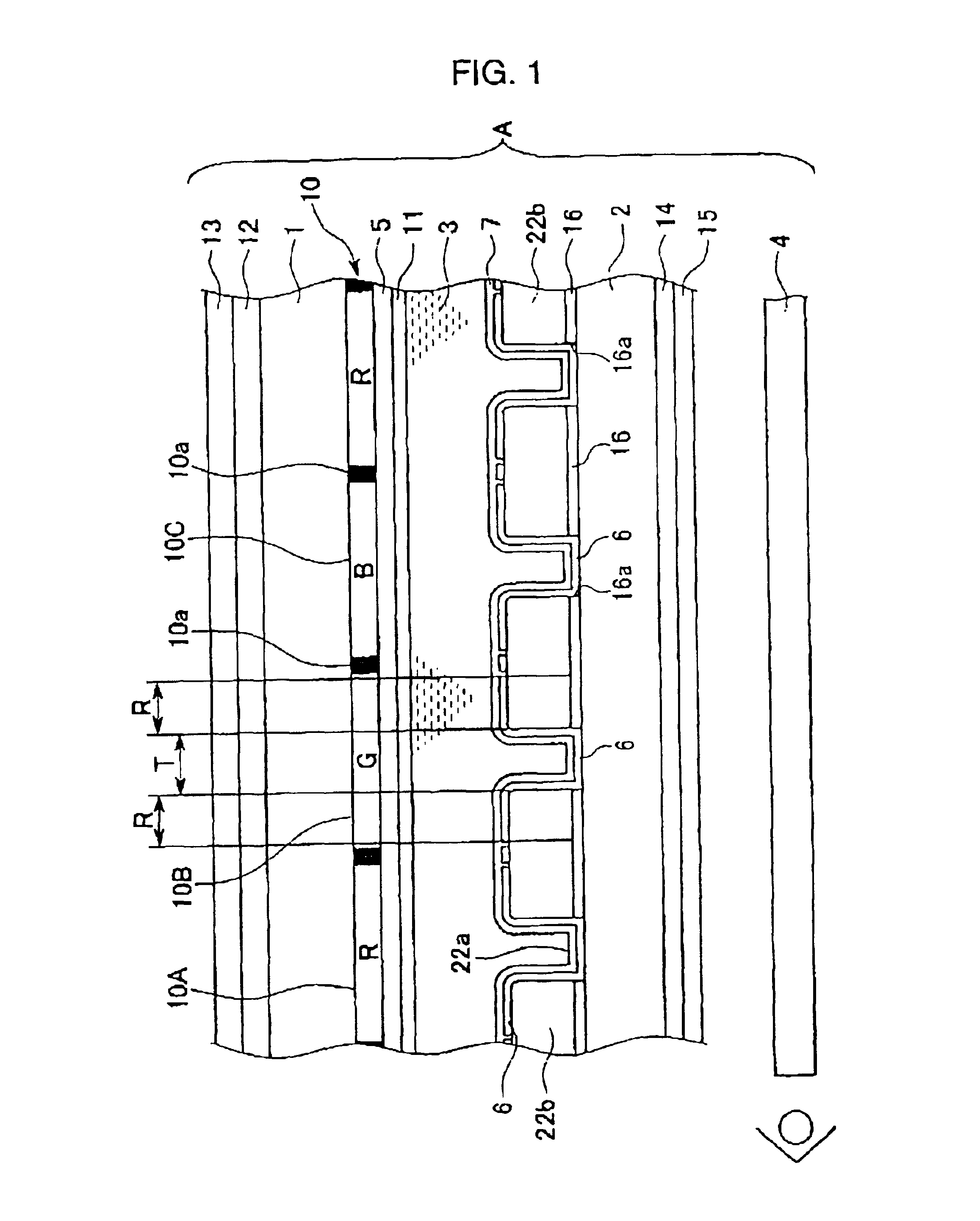
[0021]FIG. 2 is an fragmentary enlarged plan view of a reflection layer of the liquid crystal display device shown in FIG. 1.
[0022]FIG. 3 is a schematic illustration of a transmissive scattering layer of the liquid crystal display device shown in FIG. 1.
second embodiment
[0023]FIG. 4 is a schematic fragmentary sectional view of a liquid crystal display device according to the present invention.
third embodiment
[0024]FIG. 5 is a schematic fragmentary sectional view of a liquid crystal display device according to the present invention.
Login to View More PUM
| Property | Measurement | Unit |
|---|---|---|
| particle size | aaaaa | aaaaa |
| particle size | aaaaa | aaaaa |
| surface roughness | aaaaa | aaaaa |
Abstract
A liquid crystal display device 10 includes a pair of substrates 1 and 2 and a liquid crystal layer 3 held between the pair of substrates 1 and 2. The liquid crystal layer 3 includes at least two regions for displaying images, having different thicknesses from each other. One of the regions is a reflective display region R and the other is a transmissive display region T. The reflective display region R is provided with a reflection layer 16 capable of reflecting light and a transmissive scattering layer 22b capable of scattering light. The thickness of the liquid crystal layer 3 in the reflective display region R is set smaller than the thickness of the liquid crystal layer 3 in the transmissive display region T.
Description
DETAILED DESCRIPTION OF THE INVENTION[0001]1. Technical Field of the Invention[0002]The present invention relates to liquid crystal display devices and electronic apparatuses, and particularly to a technique of displaying bright and high-contrast images using a transflective liquid crystal display device having both reflective and transmissive display systems.[0003]2. Description of the Related Art[0004]Reflective liquid crystal display devices reduce power consumption because they do not have any light sources, such as a backlight. Therefore they have been used for various devices, such as portable electronic apparatuses. However, since reflective liquid crystal display devices use outside light, such as natural light and illumination light, to display images, it is difficult to view the images in dark places. Accordingly, a transflective liquid crystal display device has been proposed which uses external light in bright places, as in the conventional reflective liquid crystal disp...
Claims
Login to View More Application Information
Patent Timeline
 Patent Type & AuthorityPatents(United States)
IPC IPC(8): G02F1/13G02F1/1335G02B5/02G02B5/08G02B5/20G02F1/1333G02F1/13357H04M1/02H04M1/23
CPCG02F1/133553G02F2001/133626G02F2203/09G02F1/133626G02F1/1335
InventorMAEDA, TSUYOSHI
Owner138 EAST LCD ADVANCEMENTS LTD