Downlink telemetry system

a telemetry system and downlink technology, applied in the direction of survey, directional drilling, borehole/well accessories, etc., can solve the problems of inherently slow methods, unfavorable downlink communication, and the need to temporarily interrupt drilling, so as to reduce the time required for downlink communication and ensure the accuracy of downlink communication

Inactive Publication Date: 2005-07-19
HALLIBURTON ENERGY SERVICES INC
View PDF41 Cites 169 Cited by
  • Summary
  • Abstract
  • Description
  • Claims
  • Application Information

AI Technical Summary

Benefits of technology

[0028]The downlink telemetry system has the advantage of significantly reducing the time required for downlink communication without interrupting drilling and without interrupting uplin...

Problems solved by technology

The most significant disadvantage is that drilling must be temporarily interrupted every time a signal is sent downhole.
During directional drilling, this can be particularly undesirable because the drilling tool can only be adjusted periodically resulting in an unwanted snake-like or tortuous borehole being drilled.
Further, these methods are inherently slow because it takes time to start and stop the drilling operation, and although the goal is to instruct the downhole assembly by sending one set of signals, often the signals must be repeated since the downhole receiver does not always properly receive the instruction the first time.
Finally, this method also causes unnecessary wear and tear to the pump and associated equipment.
This system has the disadvantage of not providing a means for adjusting the flowrate through the bypass line.
Again, this pulsing system p...

Method used


Image

  • Downlink telemetry system
  • Downlink telemetry system
  • Downlink telemetry system

Examples


Embodiment Construction

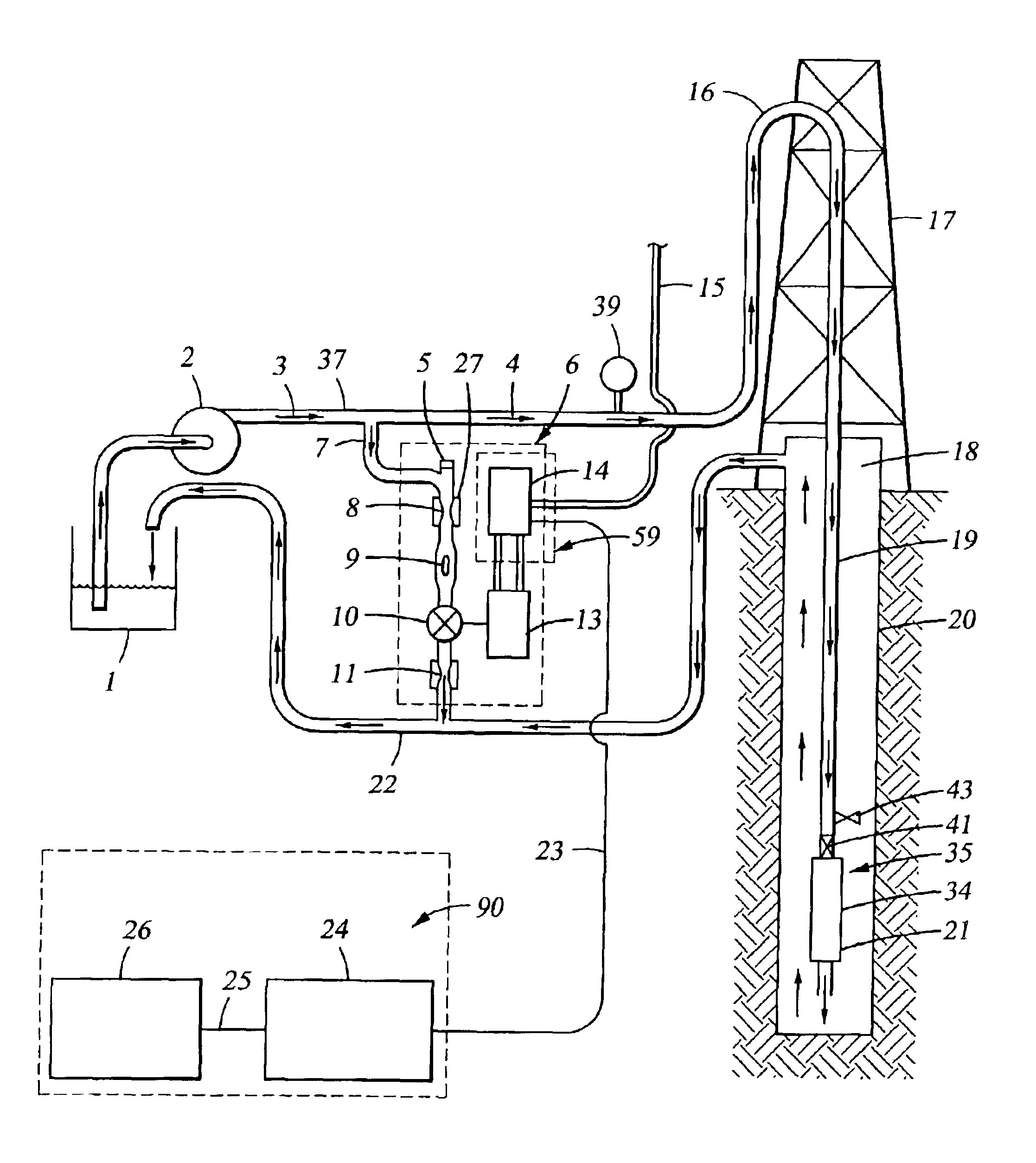
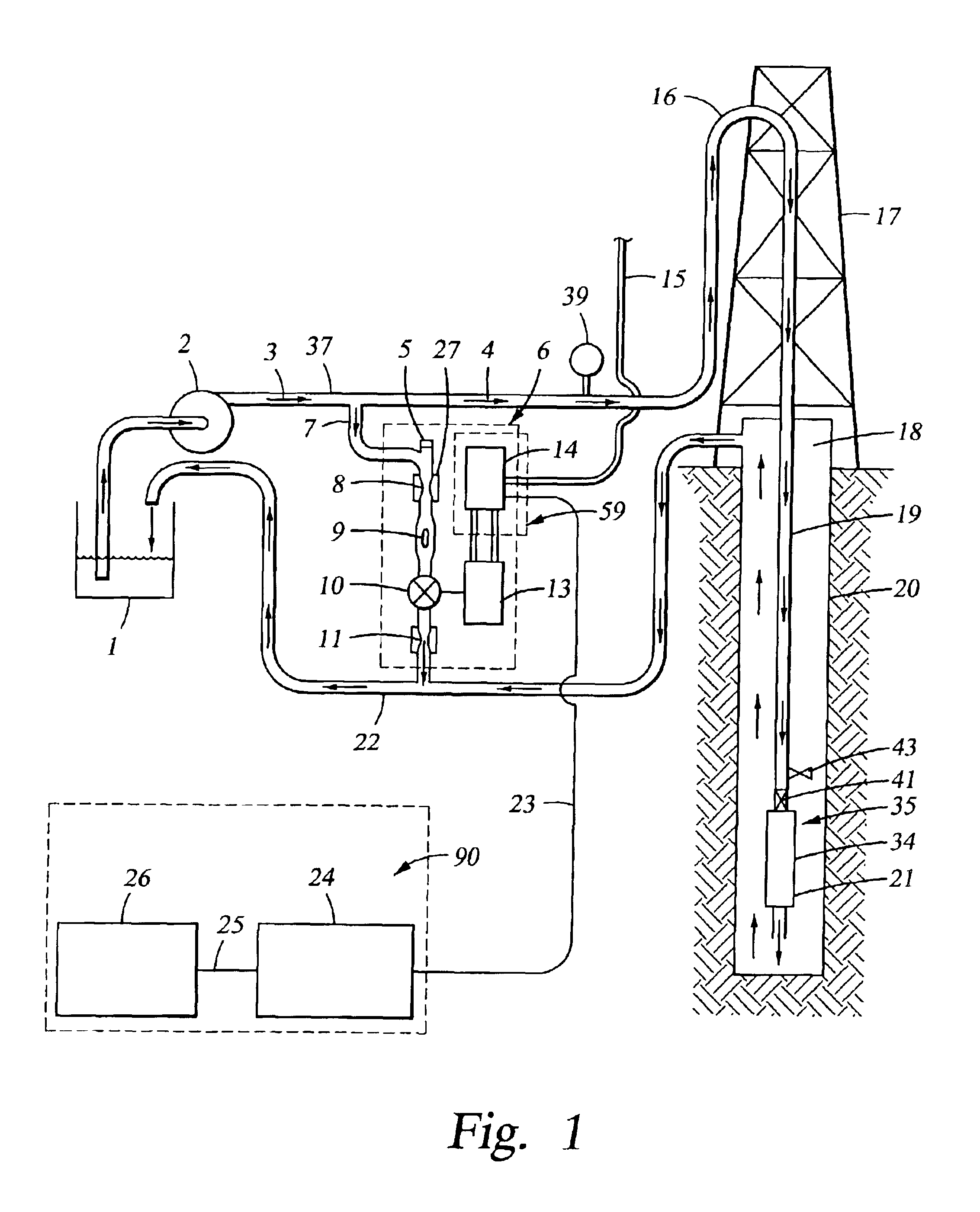
[0043]Drilling, for the purpose of extracting hydrocarbons from the earth, requires a downhole drilling assembly, which may comprise, for example, directional drilling and formation evaluation tools. To operate these drilling tools, a communication link is required between the control and data collection equipment on the surface and the downhole assembly as it drills a well below the surface of the earth.

[0044]A common way to achieve this communication link is through a method called mud pulse telemetry. Mud pulse telemetry is used for sending signals from the surface to the downhole tools (downlink) or for sending signals from the downhole assembly to the surface (uplink). Generally downlink communication sends instructions in the form of commands to the downhole tools, and uplink communication confirms the instructions received by the downhole assembly and / or provides data to the surface.

[0045]Referring initially to FIG. 1, there is depicted a typical drilling operation where mud ...


PUM


Abstract

A downlink telemetry system providing improved apparatus and methods for communicating instructions via pressure pulses from surface equipment to a downhole assembly. The apparatus comprises a surface transmitter for generating pressure pulses, a control system, and a downhole receiver for receiving and decoding pulses.
In operation, a bypass valve is opened and closed to create a series of pressure pulses received and decoded by a downhole receiver. The method significantly reduces the time required for downlink communication without interrupting drilling and without interrupting uplink communications such that simultaneous, bi-directional communication is achievable if the uplink and downlink signals are sent at different frequencies.
The telemetry scheme and algorithm provide an inventive method for filtering and decoding the downlink signals. The algorithm determines the time intervals between pulse peaks and decodes the intervals into an instruction. The algorithm also includes error checking for verifying that the instruction was properly received downhole.

Description

CROSS-REFERENCE TO RELATED APPLICATIONS[0001]Not Applicable.STATEMENT REGARDING FEDERALLY SPONSORED RESEARCH OR DEVELOPMENT[0002]Not Applicable.FIELD OF THE INVENTION[0003]The present invention relates generally to communicating between control equipment on the earth's surface and a subsurface drilling assembly to command downhole instrumentation functions. In particular, the present invention relates to apparatus and methods for communicating instructions to the drilling assembly via pressure pulse signals sent from a surface transmitter without interrupting drilling, and more particularly to apparatus and methods for detecting pressure pulses at a downhole receiver and using an algorithm to decode the pressure pulses into instructions for the downhole assembly, and still more particularly to apparatus and methods for achieving bi-directional communication between the surface equipment and the downhole assembly at a relatively rapid communication rate.BACKGROUND OF THE INVENTION[00...

Claims


Application Information

Patent Timeline
IPC IPC(8): E21B47/18E21B47/12H04H60/31
CPCE21B47/185E21B47/22E21B47/24E21B47/12E21B47/18
Inventor FINKE, MICHAEL DEWAYNEWARREN, II, DOYLE RAYMONDSUN, CILIPILLAI, BIPIN KUMAR
Owner HALLIBURTON ENERGY SERVICES INC
Why Eureka
Try Eureka