

Data-efficient and self adapting imaging spectrometry method and an apparatus thereof
a data-efficient and self-adaptive technology, applied in the field of scene capture methods and systems, can solve the problems of limited extent to which optimals are realized, and achieve the effect of low bandwidth and high accuracy
- Summary
- Abstract
- Description
- Claims
- Application Information
AI Technical Summary
Benefits of technology
Problems solved by technology
Method used
Image

Examples
first embodiment
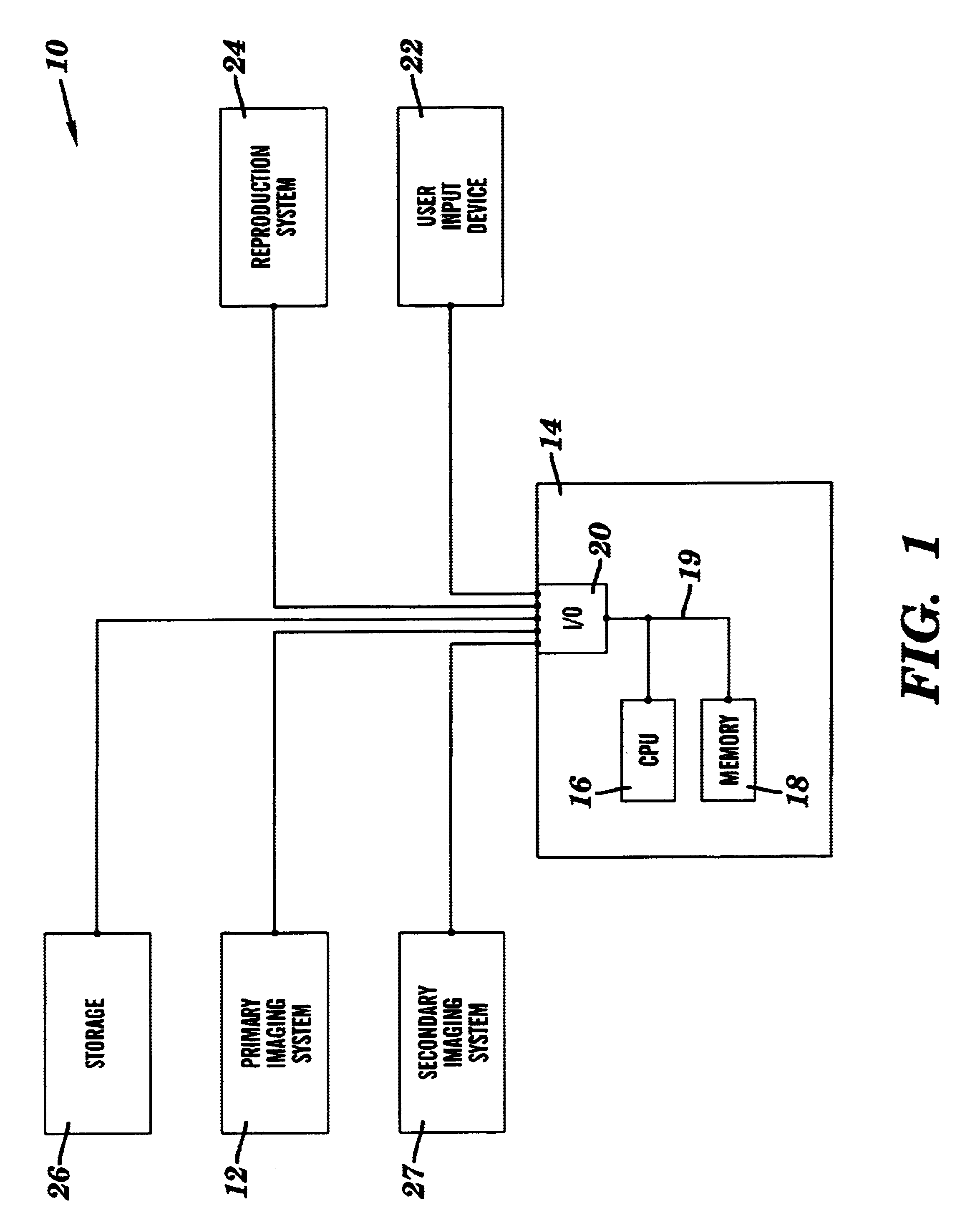
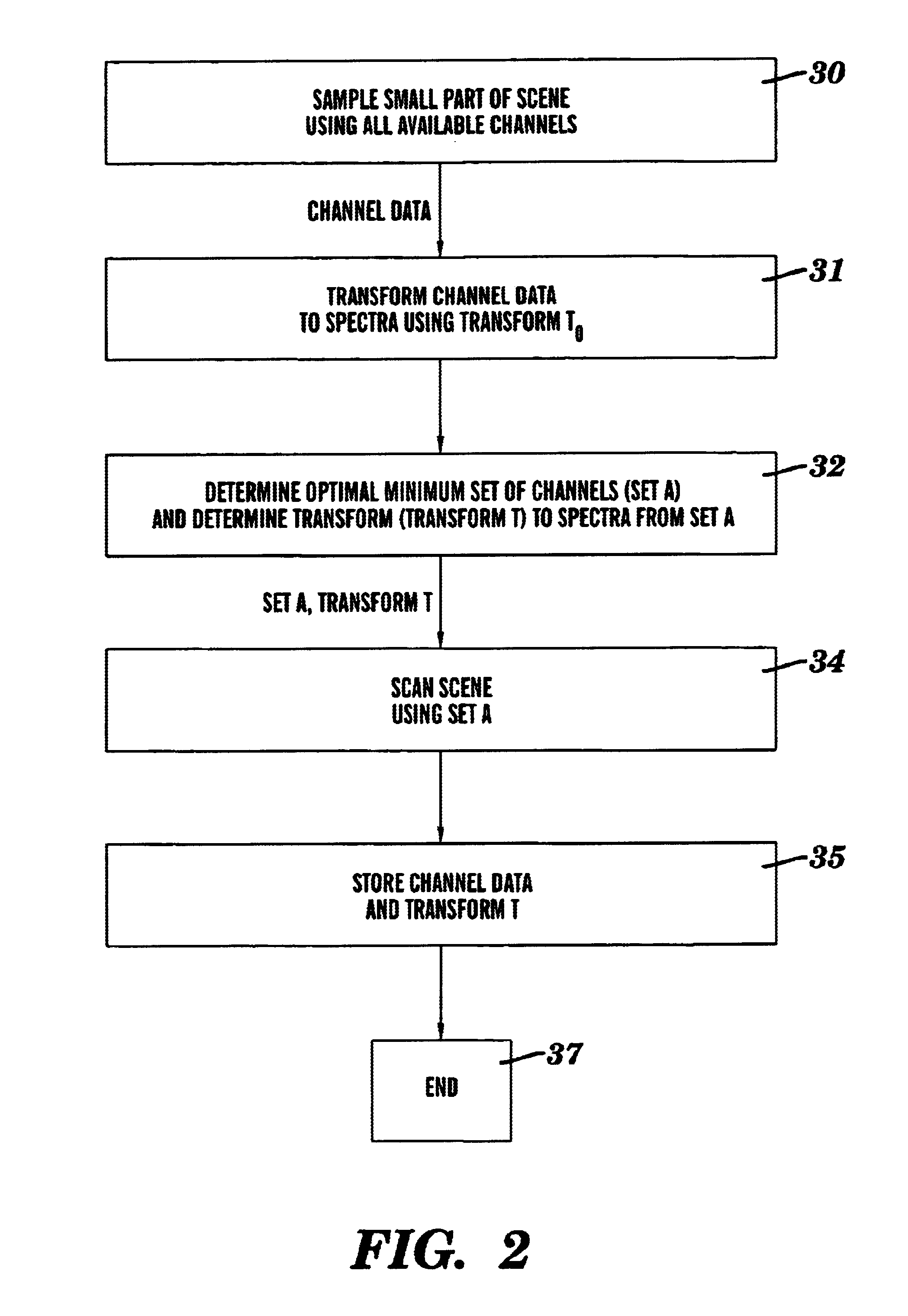
[0023]Referring to FIG. 2, a method for spectral imaging that is data efficient and self adapting in accordance with the present invention will be described. In step 30, a portion or part of a scene using all available channels is captured by the imaging system 12 and transmitted to the spectral processing system 14. Typically, the imaging system 12 will have a plethora of channels available to it. The size of the portion of the scene captured can vary as needed or desired for the particular application.
[0024]In step 31, the spectral processing system 14 transforms the channel data captured by the primary imaging system 12 to spectra using a transform t0. In this example, transform t0 was previously derived and stored in memory 18, although in other implementations it can be made known to the system 10 through other means, such as in a user initiated calibration step. By applying transform t0 to the channel data captured in step 30, highly accurate spectra for each pixel in the capt...
third embodiment
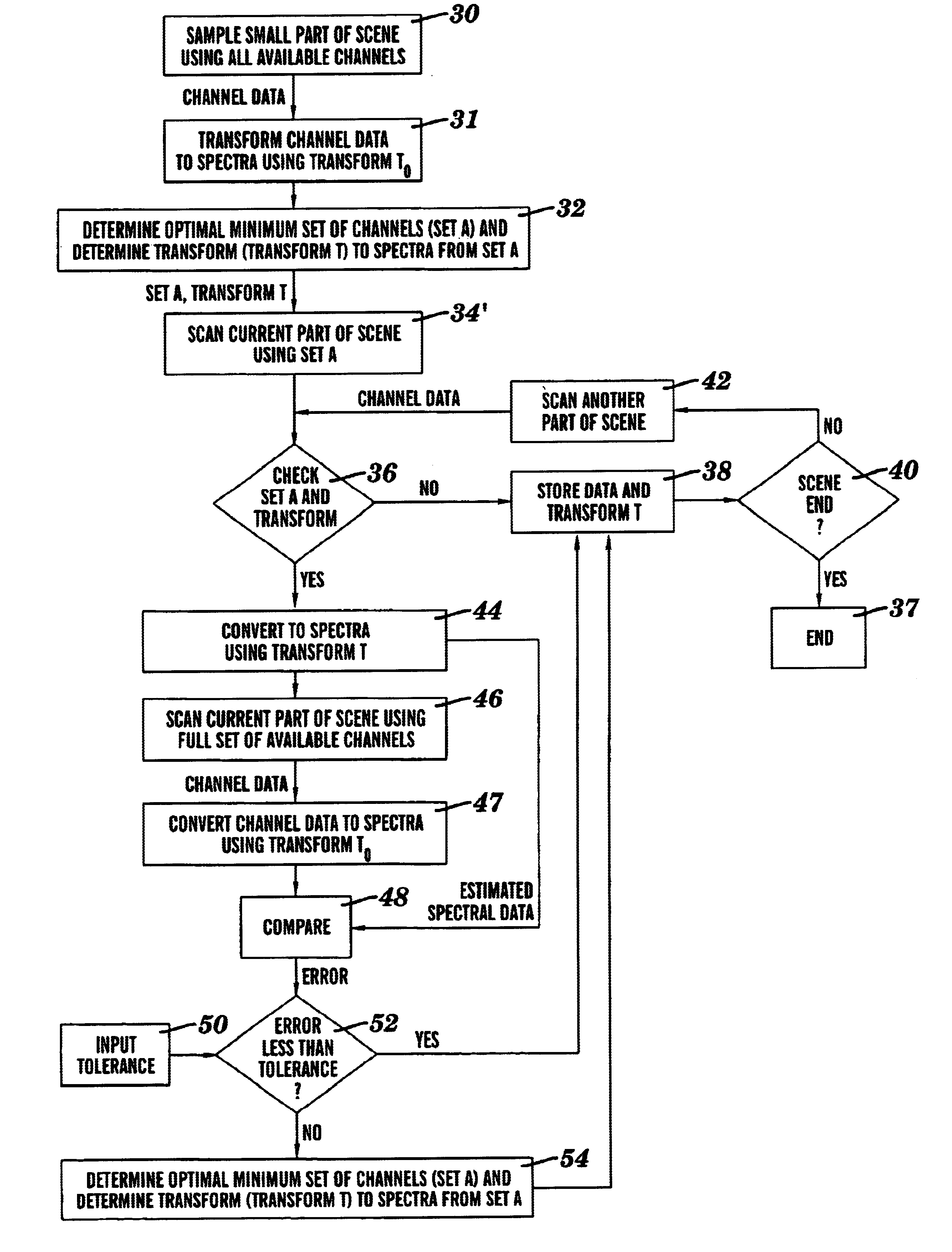
[0040]A system 10 and method for spectral imaging in accordance with the present invention is identical to the one described above and illustrated in FIGS. 1 and 3, except as described below and illustrated in FIG. 4. This particular embodiment describes the use of the present invention in a method for spectral video or spectral cinema configuration. This particular embodiment also intermittently checks to see if a high level of spectral accuracy is being realized. If insufficient accuracy is being maintained a new set of channels and a new transform is used in the primary system.
[0041]Referring to FIG. 4, in step 30′ a portion or part of a scene using all available channels is captured by the secondary imaging system 27 and transmitted to the spectral processing system 14. Typically, the imaging system 27 will have a plethora of channels available to it. The size of the portion of the scene captured can vary as needed or desired for the particular application.
[0042]In step 31′, the...
fourth embodiment
[0045]A system 10 and method for spectral imaging in accordance with the present invention is also identical to the one described above and illustrated in FIGS. 1 and 2, except as described below and illustrated in FIG. 5. This particular embodiment describes a method for capture of still spectral images where there is a primary imaging system 12 with a fixed set of channels available for capture at all times and a secondary imaging system 27 of little spatial extent, but with high spectral resolution. Unlike the embodiment described in FIG. 3, the primary imaging system 12 is not configurable in this particular embodiment and it is only the transform to spectra which can be updated periodically
[0046]Referring to FIG. 5, in step 32″ the spectral processing system 14 determines a second transform t which is used to transform the channel data to spectra for imaging. In step 35′, the spectral processing system 14 stores the transform t in storage 26, although the transform can be store...
PUM
 Abstract
Description
Claims
Application Information