Inlet and outlet duct units for air supply fan

a technology of air supply duct unit and air supply fan, which is applied in the direction of combustion process, space heating and ventilation details, domestic heating details, etc., can solve the problems of poor air flow distribution across the air heater or air heater, duct vibration, and substantial power consumption of the fan uni

Inactive Publication Date: 2005-07-26
M & I POWER TECH
View PDF38 Cites 26 Cited by
  • Summary
  • Abstract
  • Description
  • Claims
  • Application Information

AI Technical Summary

Benefits of technology

[0015]According to another aspect of the invention, an outlet duct apparatus for connecting an outlet of an air supply fan unit to an air heater unit, such as one used in a boiler, includes an elbow section of duct for transferring air from an inlet end connectable to the air supply fan unit to an opposite end of the elbow section. The elbow section bends through a smooth curve between the inlet end and the opposite end, the amount of bending being more than 60 degrees and preferably about 90 degrees. An elongate second section of the duct has an upstream first end connected to the opposite end of the elbow section and has a downstream second end which is substantially wider than the first end and is connectible to the air heater unit during use of the outlet duct apparatus for delivery of combustion air through an intake for the air heater unit. A turning vane is rigidly mounted in the outlet duct apparatus and has a curved first vane section located centrally in the elbow section and an adjoining second vane section located in the second section of duct. The second section of the duct and the second vane section extend upwardly during use of the outlet duct apparatus. There is a smooth transition between the first and second vane sections on both a front side and a rear side of the turning vane.

Problems solved by technology

Some known difficulties or deficiencies with the duct systems for delivering air to the FD fan and for delivering the pressurized air from the fan to the air heater of the boiler include substantial power consumption for the fan, relatively high operational noise created in the vicinity of the fan unit, relatively poor air flow distribution across the air heater or air heaters and duct vibrations.
Because of the configuration of these known silencers and because air follows the path of least resistance through an air duct, the flow through the passageways formed by the splitters is not uniform.
There can also be airflow induced vibrations in the inlet duct unit due to a sudden change in the velocity of air.
With respect to the conventional form of connecting duct between the FD fan and the air heaters of the boiler, the conventional duct system does not provide a smooth flow of the high velocity air from the fan unit.
The reaction to this high velocity air creates a flow barrier and also creates very high turbulence in the transition section above the elbow section.
This turbulence causes a very high pressure drop and noise in the duct.

Method used


Image

  • Inlet and outlet duct units for air supply fan
  • Inlet and outlet duct units for air supply fan
  • Inlet and outlet duct units for air supply fan

Examples


Embodiment Construction

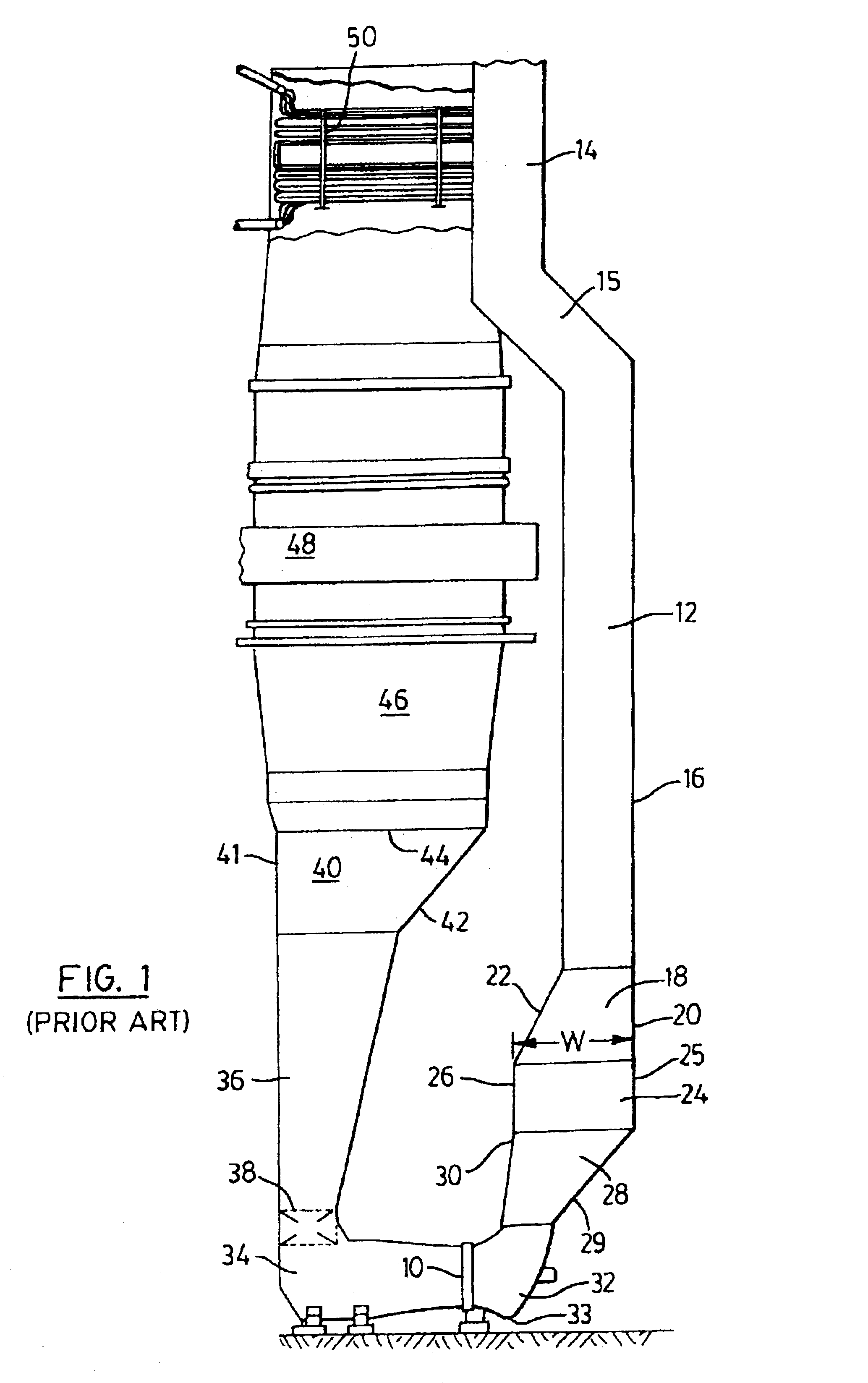
[0035]FIG. 1 illustrates a known system for delivering combustion air to a boiler unit by means of a standard forced draft fan located at 10. Fresh outside air is drawn into the inlet end of the fan 10 by means of a long, generally vertical inlet duct 12. As illustrated, this inlet duct has a straight upper section 14, a short sloping section 15 and a long, vertical intermediate section 16 that extends down to a transition section 18. The transition section has a vertical side wall at 20 and a downwardly and outwardly sloping side wall at 22. The transition section 18 widens the air passageway substantially to a width W which in one embodiment is about 13 feet. Connected to the bottom of the transition section is a known, splitter silencer unit indicated generally at 24 and explained in more detail hereinafter with reference to FIGS. 2 and 6. The splitter silencer has four vertical exterior sides, including opposing sides 25 and 26. Located below the silencer unit is another transit...


PUM


Abstract

Duct units for delivery of air to an air supply fan and for connecting this fan to an air heater unit are disclosed. The duct unit for delivering air in one version has a narrow first section, a second, transition-type section and a wide sound attenuating, third section with these three sections extending generally vertically. Spaced apart splitters containing sound attenuating material and having side walls of perforated metal are mounted in the third section. The splitters include a central splitter and outer splitters with the latter converging inwardly towards a central axis of the third section. This duct unit also has an elbow-shaped duct section connected to the third section at its upstream end and connectible to the fan at its downstream end. In another version, the duct unit has a single, elongate splitter that extends longitudinally along at least a major portion of a second duct section and that bends through a smooth curve. The outlet duct apparatus has an elbow section of duct that bends through a smooth curve and an elongate second section connected to the elbow section. An elongate turning vane is mounted in the outlet duct and has a substantially curved first vane section and a second vane section that extends substantially upwardly.

Description

BACKGROUND OF THE INVENTION[0001]This invention relates generally to duct units, including sound attenuating duct units for transferring air or gases to a fan unit, including such duct units for delivering air to and from an air supply fan unit for use in conjunction with air heaters, such as those used in boiler systems.[0002]It is known to provide large utility and industrial boilers (steam generators) which are used for power and co-generation. These boilers can be oiled fired with water tubes extending through the boiler and the water therein being heated by means of suitable air heaters. Large amounts of combustion air can be provided to these air heaters by means of a forced draft fan unit (herein sometimes referred to as a “FD fan”). This fan unit is powered electrically and can be arranged to rotate about a horizontal axis. It is known to deliver fresh air from the atmosphere through a long, vertically extending air duct that may include a splitter-type sound attenuating sec...

Claims


Application Information

Patent Timeline
Patent Type & Authority Patents(United States)
IPC IPC(8): F04D29/40F23L5/02F04D29/54F23L5/00
CPCF04D29/542F04D29/545F23L5/02Y10S454/906F04D29/544
Inventor HAN, MING HUIGUAR, PRADEEP
Owner M & I POWER TECH
Why Eureka
Try Eureka