Tool and toolholder for chip forming machining

a tool and tool holder technology, applied in the direction of manufacturing tools, shaping cutters, transportation and packaging, etc., can solve the problems of dimensional deviation, high rotational speed, and the inability of milling tools to be unlimitedly large in diameter

Inactive Publication Date: 2005-07-26
SANDVIK INTELLECTUAL PROPERTY AB
View PDF11 Cites 46 Cited by
  • Summary
  • Abstract
  • Description
  • Claims
  • Application Information

AI Technical Summary

Benefits of technology

[0008]In a first aspect, the present invention aims at providing a tool intended for chip forming or chip removing machining, having an improved connecting interface between the holder of the tool and a cutting body detachably connected thereto. Therefore, a primary aim of the invention is to provide a tool having a connecting interface which has high precision, more precisely by ensuring a controlled and reliable contact between the flanks of co-operating ridges independently of such minor dimensional deviations that in practice may arise in serial production of the tool. The connecting interface should, in this connection, endure extremely high mechanical loads as well as permit a stable and well-defined fixing of the cutting body on the holder. A further aim is to provide a tool having a connecting interface which enables production of comparatively thin cutting inserts without the same running an obvious risk of disintegrating or cracking during use. The geometry of the connecting interface should, among other things, not cause considerable tensile stresses in the material of the cutting body. Yet another aim of the invention is to provide a tool, the cutting body of which may be fixed in an exact way without the connecting surfaces necessarily needing to be ground.

Problems solved by technology

In order to carry out a milling operation at such a cutting speed, a relatively high rotational speed is required in that the milling tools cannot be of an unlimitedly large diameter.
Thus, centrifugal and unbalance forces play a central role in high-speed rotating tools, such as milling tools for aluminium machining.
However, in practical manufacturing of the holders and cutting bodies, respectively, of the tools (which is carried out in different places), dimensional deviations may occur, which entail that the contact points or surfaces between the flanks of the ridges are established in an uncontrolled and unsatisfactory way when the connecting surfaces are brought to engagement with each other at the assembly of the cutting body on the holder.
This can, among other things, result in the interface between the cutting body and the holder simply being sheared off because the material in the peaks or apex portions of the holder ridges fails.
Furthermore, angular errors may at times arise inasmuch as nearby flanks may get different angles, whereby gaps arise between the same.
Minor dividing or form errors may likewise arise.
The consequences of uncontrolled and mediocre contact between the ridges may become hazardous when the tool is operated at high rotational speed.
For instance, a screw arranged for clamping the cutting body may be exposed to considerable tensile load, and become elongated as a consequence of the ridges in the respective connecting surfaces moving in relation to each other; something which may result in the screw giving away and the cutting body coming loose from the holder and being thrown out with great force as a consequence of the centrifugal force.
It may also occur that the ridges in the usually hard material of the cutting body crack.
Another disadvantage of tools having connecting surfaces of the previously known type is that the bottom spaces of the individual grooves of the connecting surface of the cutting body are comparatively deep and have an inappropriate geometry.
This implies limited possibilities to form such connecting surfaces on comparatively thin, flat, and thereby light cutting inserts of the type that is desirable for use in high-speed rotating milling tools.
Among other things, there is a considerable risk that the cutting inserts disintegrate or crack if the grooves are too deep in relation to the thickness of the cutting inserts.
For these reasons, the connecting interface described in SE-9404266-0 is not suited for use in flat, comparatively thin cutting inserts intended for high-speed rotating tools.
However, also in this case the contact lines between the convex flanks of an individual ridge and the plane flank surfaces of a co-operating groove are located high in the groove; something which results in that the joint between the cutter head and the shaft may become unstable and unreliable.
Furthermore, the ability of the connecting interface to accept dimensional deviations from the production process is extraordinarily limited.

Method used


Image

  • Tool and toolholder for chip forming machining
  • Tool and toolholder for chip forming machining
  • Tool and toolholder for chip forming machining

Examples


Embodiment Construction

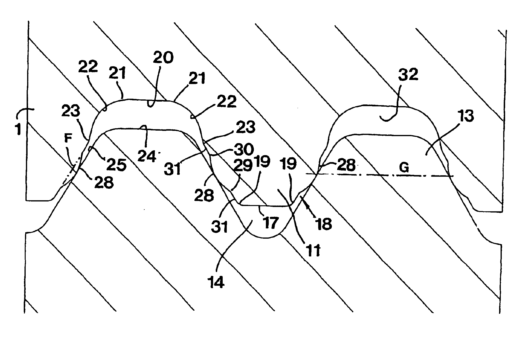
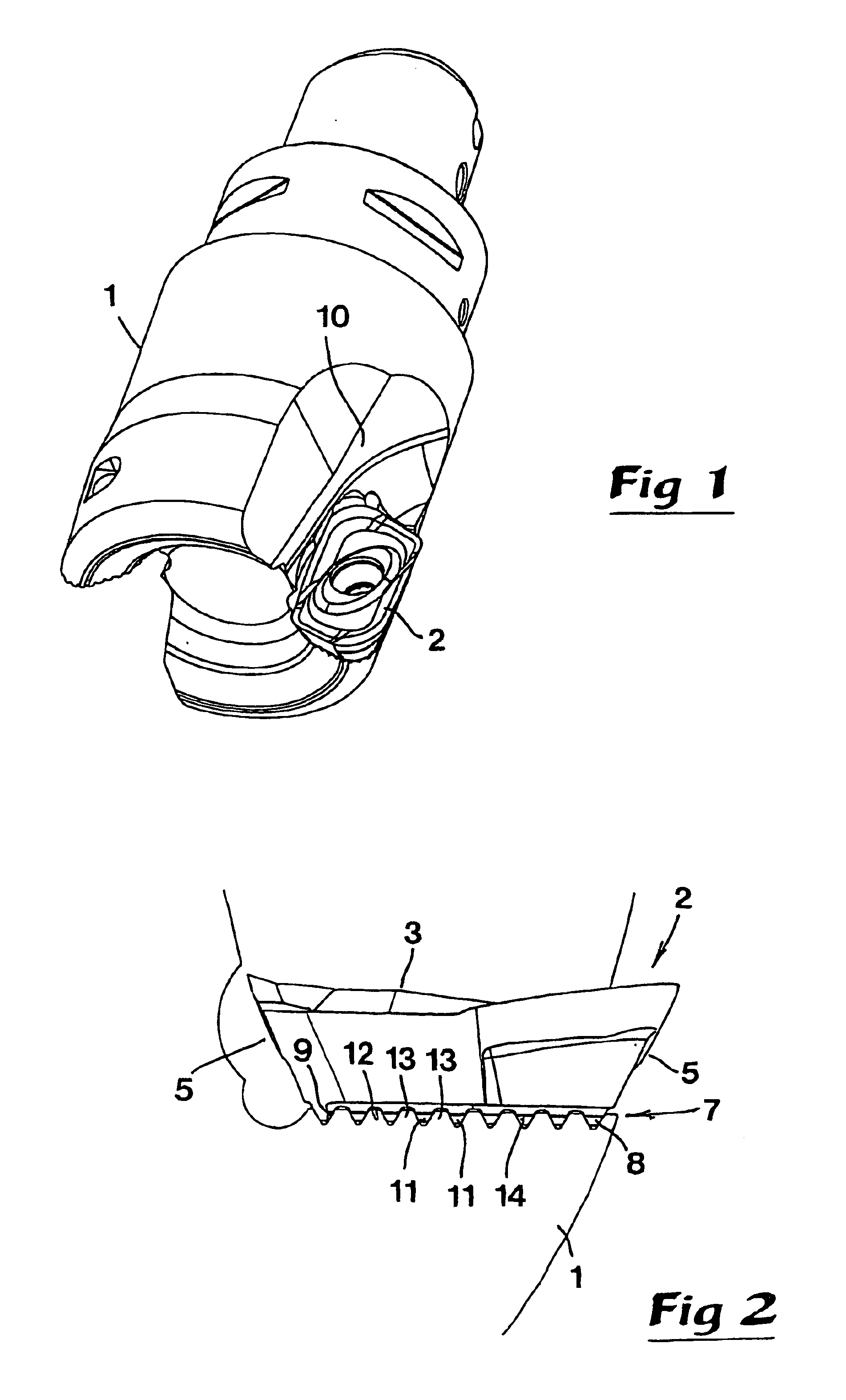
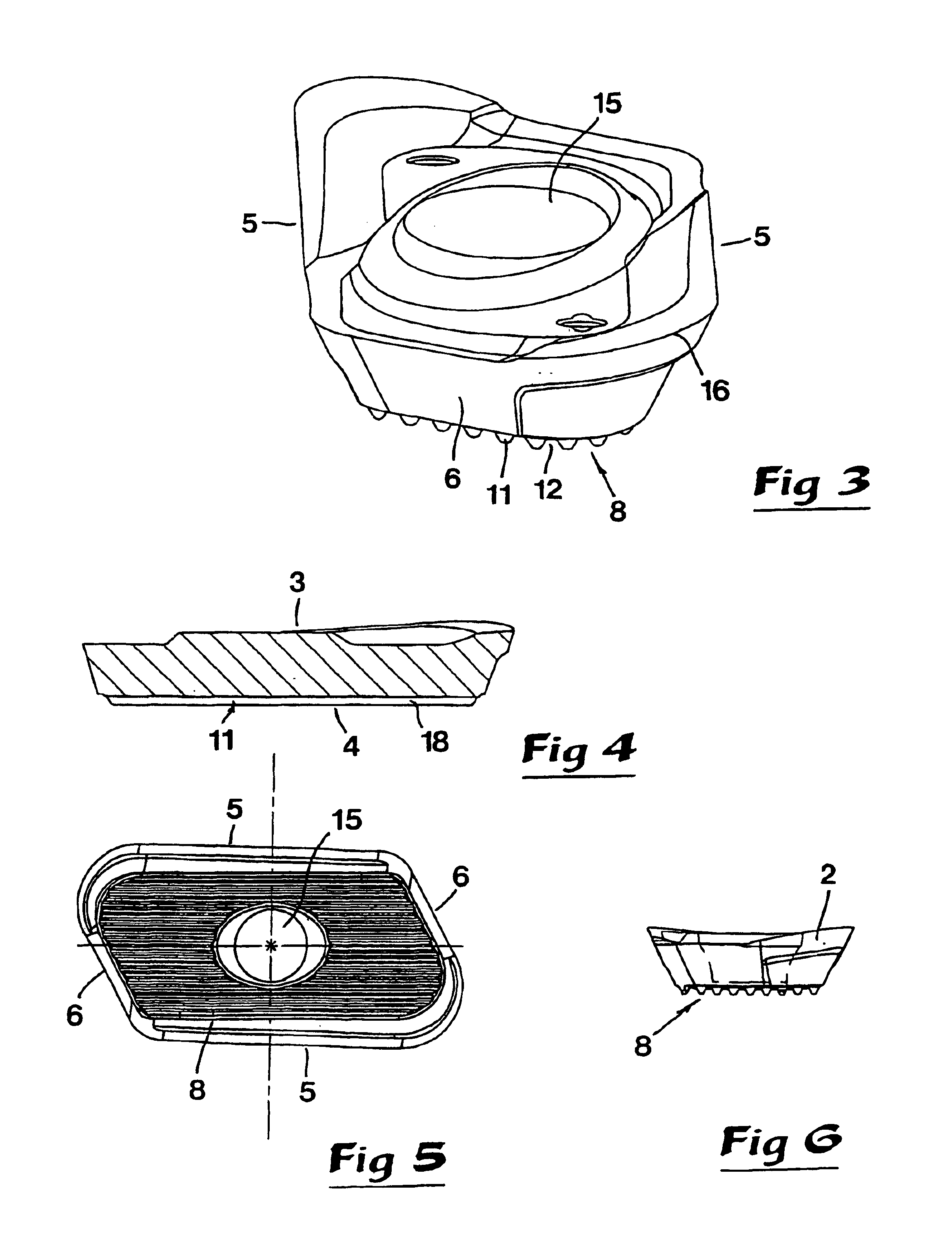
[0032]In FIGS. 1 and 2, numeral 1 designates a holder in the form of a milling head, which is part of a tool for chip removing machining. On said milling head, a plurality of cutting inserts are assembled, one of which is shown with the general reference designation 2. Although the geometry of said cutting insert may be fairly complicated, in particular on the topside of the cutting insert, the cutting insert consists of a flat cutting insert of the type, which has a comparatively limited thickness in relation to other dimensions. In FIGS. 2-6, numerals 3, 4 designate the top and bottom sides of the cutting insert, while 5, 6 designate two different types of peripheral sides, viz. long sides and short sides, respectively. Thus, in the example, the cutting insert is generally polygonally shaped. In round cutting inserts, only a single, circumfering side surface is found.

[0033]The cutting insert 2 is connected to the cutter head via an interface or a connecting interface, in its entir...


PUM

PropertyMeasurementUnit
distanceaaaaaaaaaa
angleaaaaaaaaaa
radius R1aaaaaaaaaa

Abstract

An indexible cutting insert has a connecting surface formed by alternating parallel ridges and grooves. Each ridge is defined by a pair of flanks which converge in an outward direction. Each ridge includes a convexly curved surface portion for making line contact with a corresponding ridge of a support surface. The convexly curved surface is spaced from outer and inner ends of the respective flank.

Description

TECHNICAL FIELD OF THE INVENTION[0001]In a first aspect, this invention relates to a tool intended for chip removing machining of the type that comprises a holder and a cutting body having a first connecting surface which comprises several first long, narrow ridges spaced-apart via grooves, which ridges are mutually parallel and have a cross-section-wise tapering shape, and which surface is arranged to engage with a second connecting surface of the holder or a part connected to the same, which second surface is formed with similar parallel second ridges and grooves with the aim of achieving rigid fixing of the cutting body in relation to the holder, whereby the individual ridge in the respective connecting surface is delimited by an apex and two opposite flanks, which extend towards spaced-apart bottom spaces in the grooves.[0002]Tools of the above generally mentioned kind are usually used for machining work pieces of metal, such as steel, aluminium, titan, etc. The holder of the to...

Claims


Application Information

Patent Timeline
Patent Type & Authority Patents(United States)
IPC IPC(8): B23C5/10B23C5/20B23C5/16B23C5/22B23B27/16B23B51/00
CPCB23C5/109B23C5/207Y10T407/23Y10T407/2274Y10T407/1936B23C2200/165B23C5/202B23C5/205
Inventor ARVIDSSON, PEDERJOHANSSONENQUIST, LARS-ERIK
Owner SANDVIK INTELLECTUAL PROPERTY AB
Why Eureka
Try Eureka