
Joint connector and its terminals

a connector and terminal technology, applied in the direction of coupling contact members, coupling device connections, electrical devices, etc., can solve the problems that the stable contact between the coupling member b>75/b> and the female terminal b>73/b> might not be maintained for a long time, so as to improve the attachability and reliability between the terminal and the coupling member, the depth of the connector housing can be shortened and the effect of improving the reliability

Inactive Publication Date: 2005-07-26
YAZAKI CORP
View PDF27 Cites 9 Cited by
  • Summary
  • Abstract
  • Description
  • Claims
  • Application Information

AI Technical Summary

Benefits of technology

[0020]Moreover, since the coupling member is slidably supported, the joint circuit component can slide smoothly. At the slide end, the coupling member is clipped by the resiliently clipping member of the terminal, so that the terminal and the coupling member are jointly connected with each other. Therefore, attachability and reliability between the terminal and the joint connector are improved.
[0038]According to the above composition, the coupling member and the terminal can be assembled in parallel with each other, so that an inner space of the connector housing can be saved to prevent the connector housing from being bulky in the vertical direction. Especially, when the terminal as described above is used, in addition to the ability to prevent the connector housing from being bulky, a depth of the connector housing can be shortened. Further, since the connector housing can be prevented from being bulky in a vertical direction, a compact joint connector can be offered. Further, the attachability and the reliability between the terminal and the coupling member can be improved.

Problems solved by technology

However, the conventional joint connector shown above has a problem as follows, which should be solved.
Further, there is a worry that a stable contact between the coupling member 75 and the female terminal 73 might not be maintained for a long time.

Method used


Image

  • Joint connector and its terminals
  • Joint connector and its terminals
  • Joint connector and its terminals

Examples


Embodiment Construction

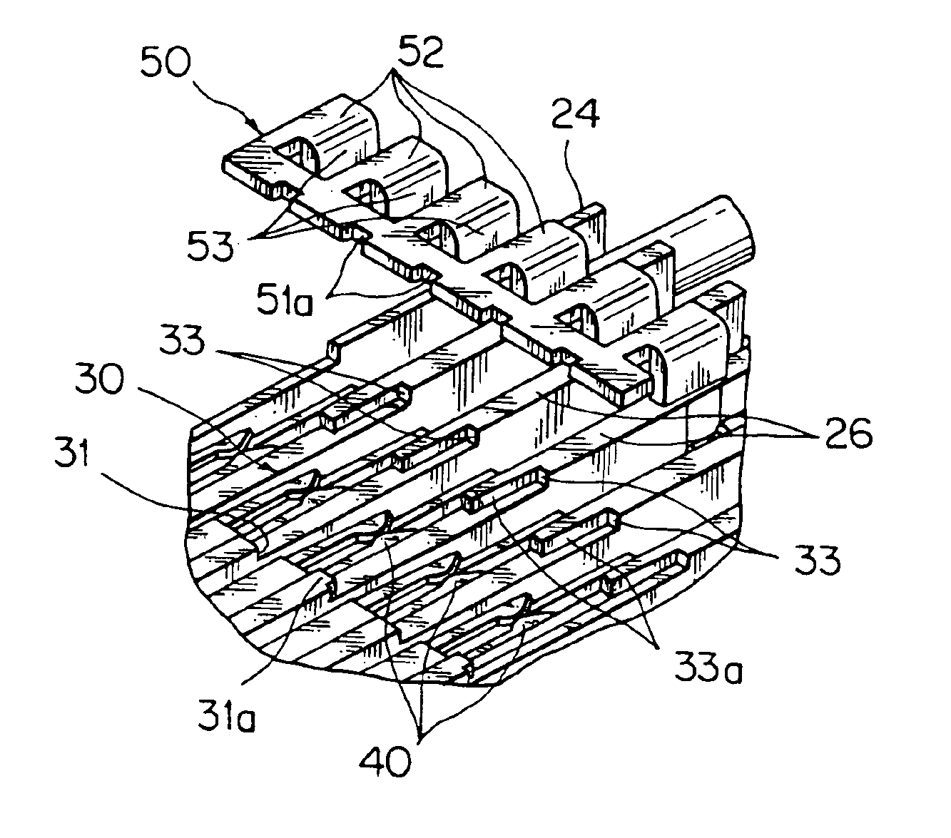
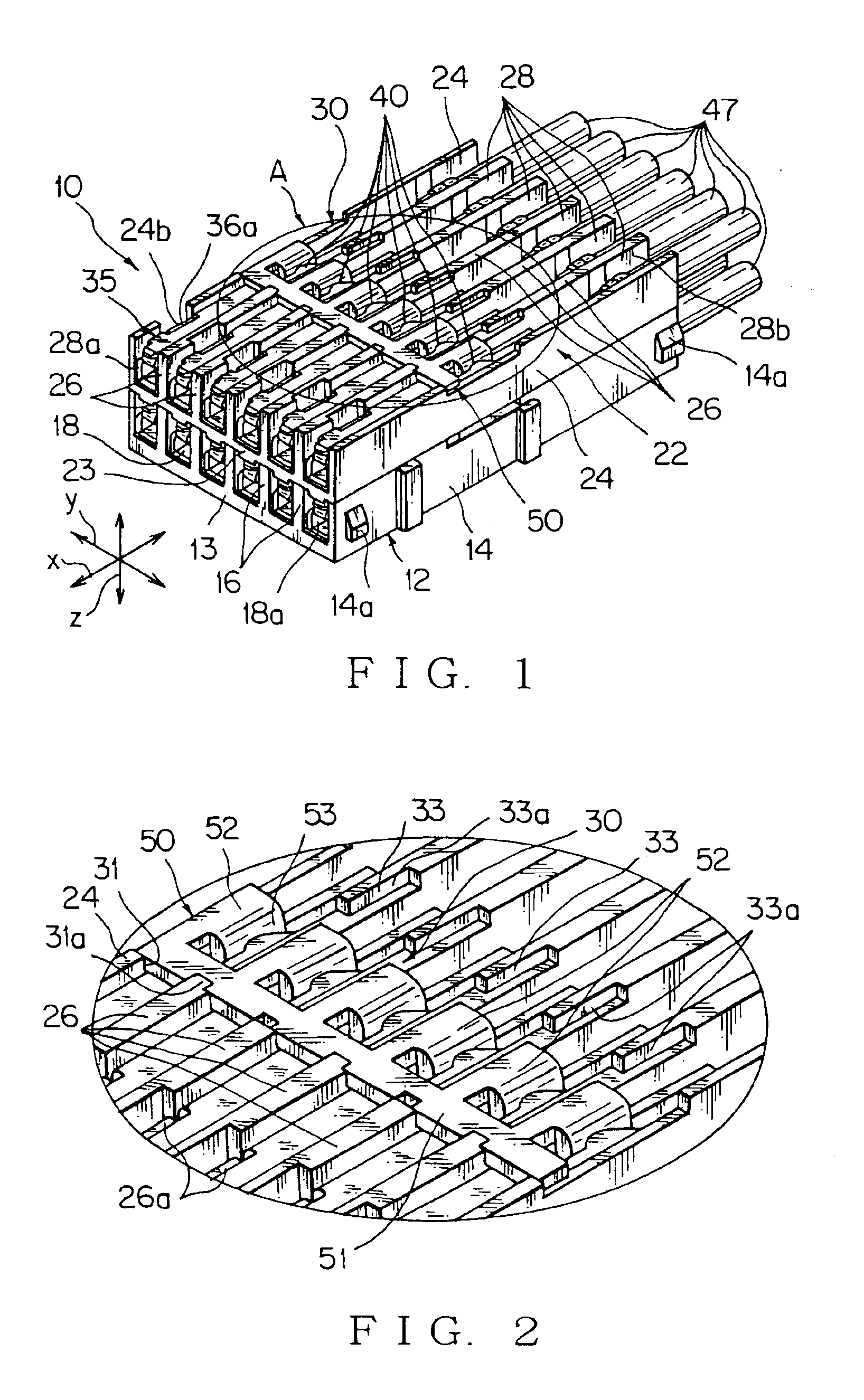
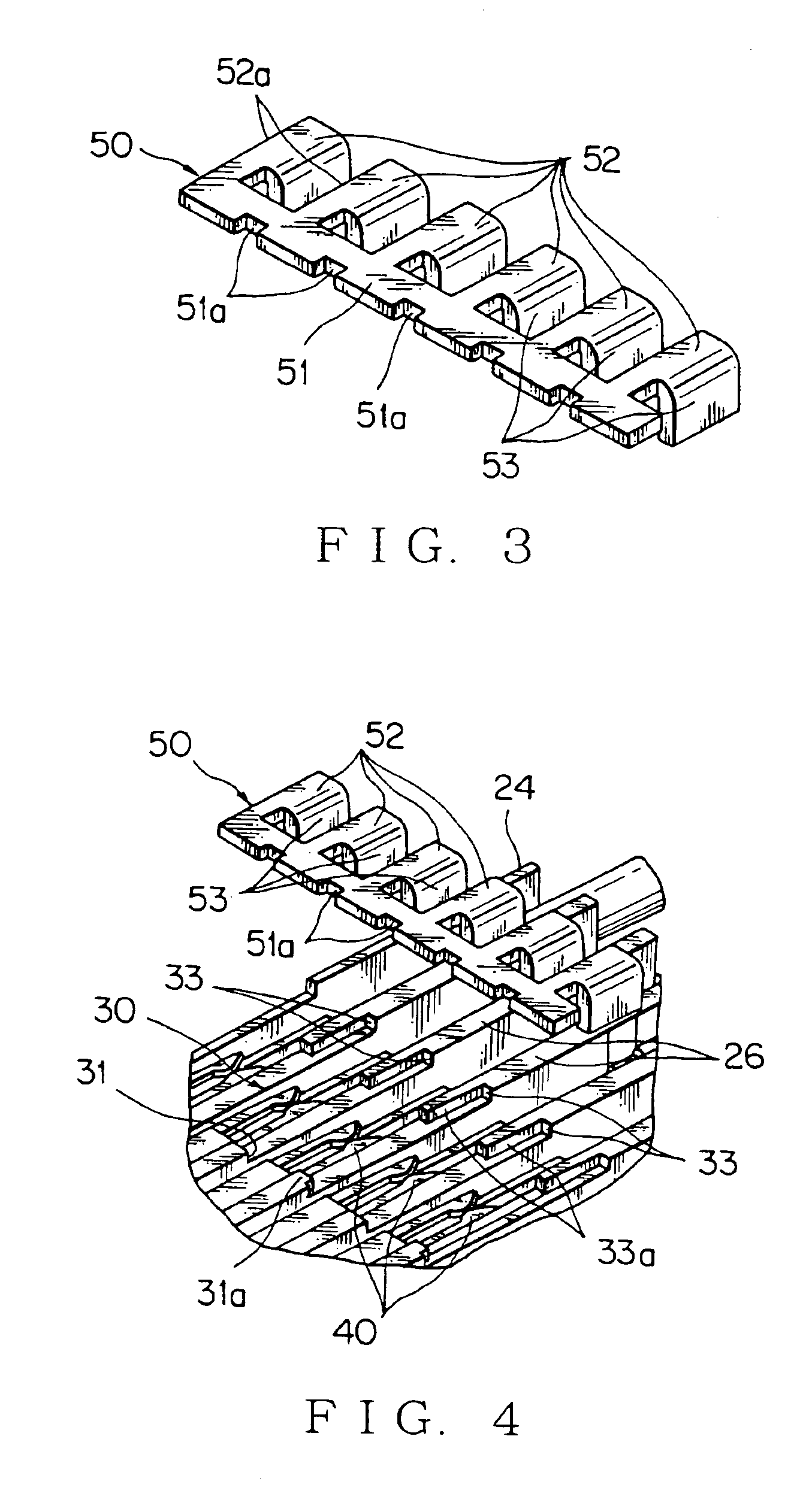
[0051]One embodiment of this invention will now be described with reference to the attached drawings. Each of FIGS. 1 to 5 shows one embodiment of a joint connector according to this invention, and FIGS. 6 and 7 shows one embodiment and one modified embodiment respectively of a terminal according to this invention.

[0052]The joint connector is a connector which jointly connects a coupling member to a plurality of terminals received in terminal receiving chambers respectively, whereby the terminals are short-circuited intentionally to be electrically common inside the connector housing, and connects to a mating connector (not shown) to make a joint circuit. As the mating connector, for example, a connector connected to an end of a wire harness, or a connector directly connected to an apparatus such as a motor, can be used.

[0053]The terminal is a metal terminal having two functions at once, one function is to connect wire harnesses with each other by connecting with a mating terminal, ...


PUM


Abstract

A notch 30 is provided at partitions 16, 26 and side walls 14, 24 to support slidably a coupling member 50 from a slide start to a slide end of the notch 30, said partitions and side walls partitioning terminal receiving chambers 18, 28. A resiliently clipping member 40 is provided at a terminal 35 to clip the coupling member 50 at the slide end of the notch 30. Further, the coupling member 50 has a thin joint piece, slidably contacting piece continued to the joint piece in a same plane, and a vertically contacting piece formed perpendicular to the slidably contacting piece. A wall to prevent the coupling member 50 from lateral displacement is provided at the notch 30, said wall being contacted with a side part of the coupling member 50.

Description

FIELD OF THE INVENTION[0001]This invention relates to a joint connector and its terminals being applied to vehicles, such as a car, for forming a joint circuit either between wire harnesses interconnecting with each other, or between a wire harness and an apparatus.DESCRIPTION OF THE RELATED ART[0002]FIGS. 8 to 11 show some embodiments of the conventional technology relevant to this kind of joint connectors.[0003]FIG. 8 (Patent document 1) shows a sectional view of a state where the joint terminal is inserted into a cavity in a connector housing. In a connector housing 60, a plurality of terminal receiving chambers 61 divided by partitions in a lattice shape are arranged in a vertical direction and in a horizontal direction (only one terminal receiving chamber 61 is shown in FIG. 8), and a female terminal 65 connected to an end of an electric wire 66 is received by each terminal receiving chamber 61. A cavity 62 communicates with the terminal-receiving chamber 61 through a narrow pa...

Claims


Application Information

Patent Timeline
Patent Type & Authority Patents(United States)
IPC IPC(8): H01R31/08H01R31/00H01R13/11
CPCH01R31/085
Inventor TAKAHASHI, TOSHIHARUSUZUKI, MOTOYOSHI
Owner YAZAKI CORP
Learn More