Simplified device for regulating the flow rate of medical liquid directed towards a patient

Inactive Publication Date: 2005-07-26
GVS SPA
View PDF7 Cites 8 Cited by
  • Summary
  • Abstract
  • Description
  • Claims
  • Application Information

AI Technical Summary

Benefits of technology

[0005]An object of the present invention is to provide a device for regulating the flow rate of the medicinal liquid directed towards a patient which is of more simple

Problems solved by technology

The known devices of the aforesaid type hence comprise a body with five elements (the three portions and the two seal members between them) which is costly to produce and assemble, is costly to stock and is of large dimensi

Method used


Image

  • Simplified device for regulating the flow rate of medical liquid directed towards a patient
  • Simplified device for regulating the flow rate of medical liquid directed towards a patient
  • Simplified device for regulating the flow rate of medical liquid directed towards a patient

Examples


Embodiment Construction

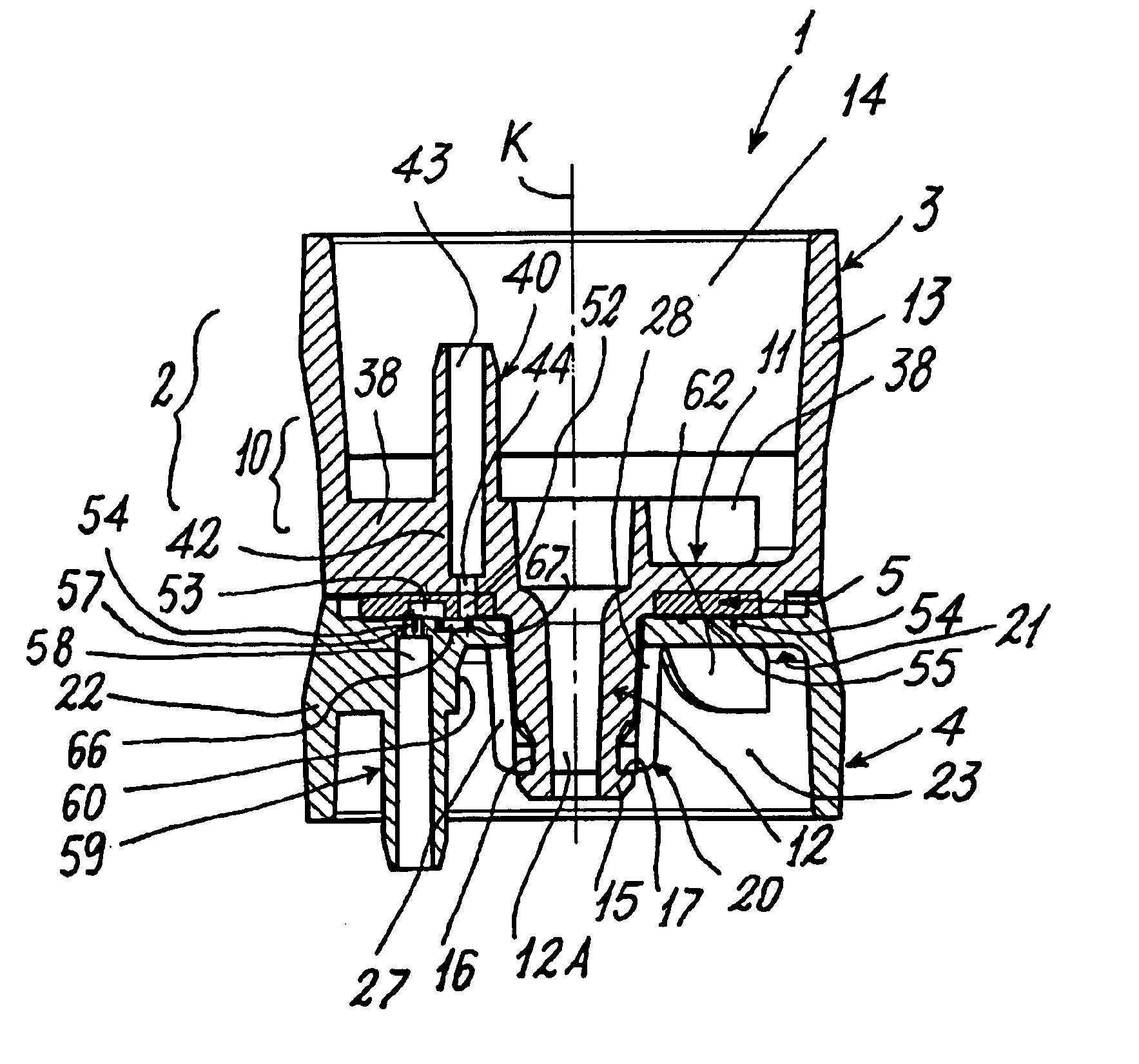
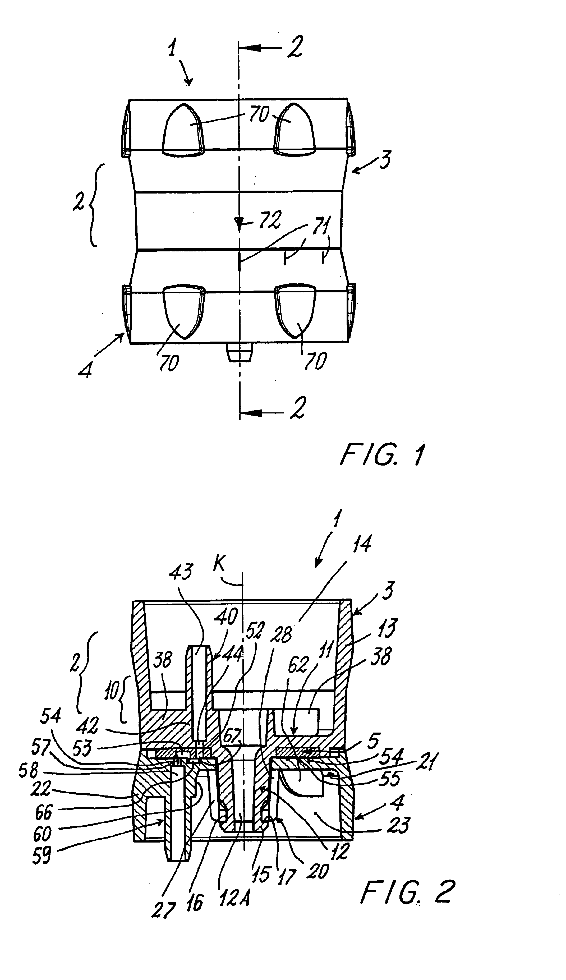
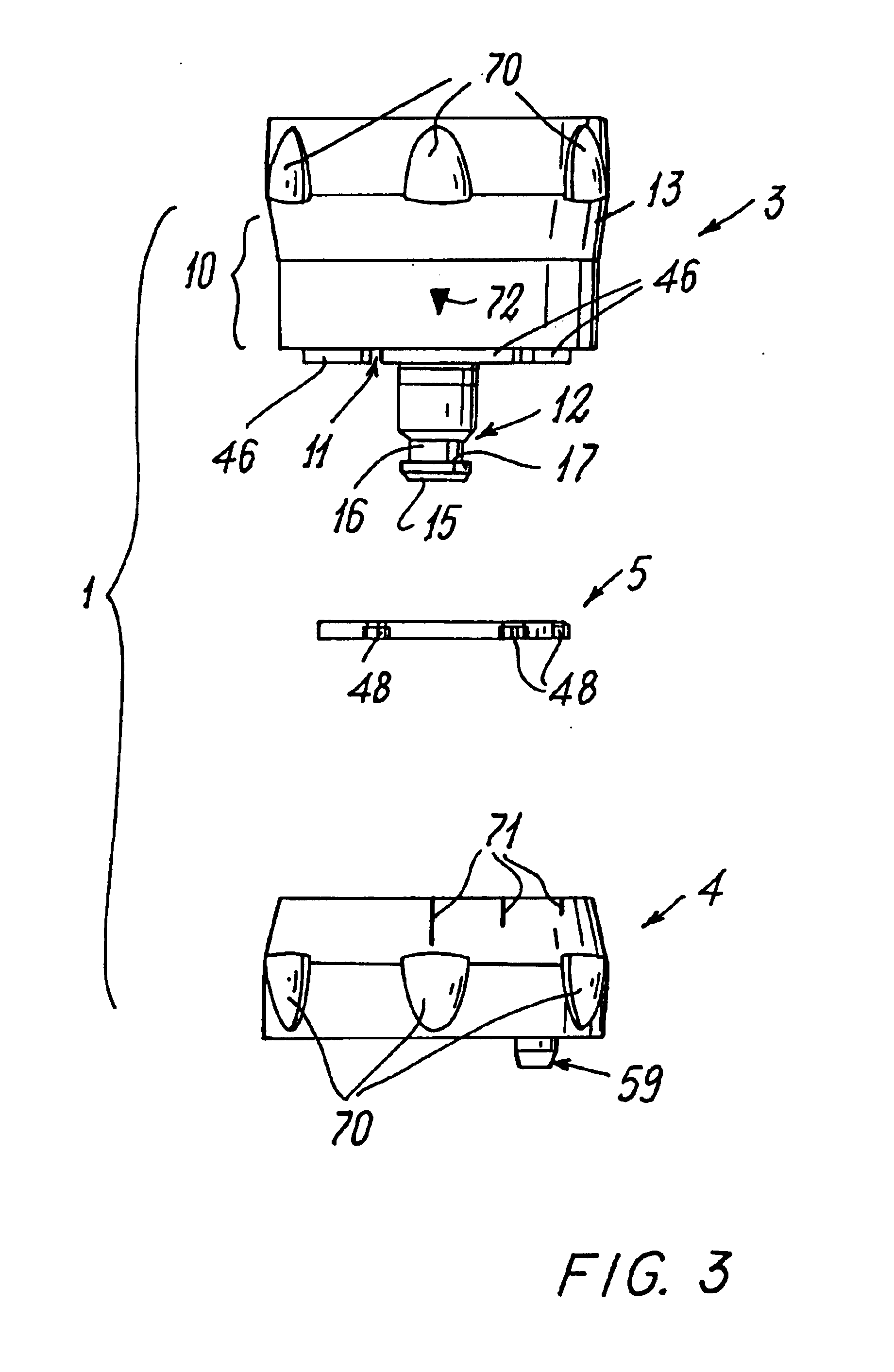
[0018]With reference to said figures, a device according to the invention is indicated overall by 1. It comprises a body 2 presenting a first part or portion 3 to be connected to a first conduit (not shown) of a medical infusion line connected to a container or reservoir of medicinal liquid, and a second part or portion 4 to be connected to a second conduit of said line (also not shown) carrying the said liquid to a patient.

[0019]Between the first part 3 and the second part 4 there is a seal element or gasket 5. These parts are connected together but are torsionally independent of each other such that they can rotate about a common axis K or longitudinal axis of the body 2 (see for example FIG. 5). To achieve said connection, the first part 3 comprises a structure 10 of substantially cup shape and having a flat portion 11 from which there projects towards the part 4 a connection element 12 hollow at 12A, and from the edge of which there rises a wall 13 defining a cavity 14. The conn...


PUM


Abstract

A device for regulating the flow rate of a liquid in a medical infusion line, includes a body presenting elements for its connection to a first and to a second conduit connected to a container for the liquid and directed to a patient respectively, the body presenting a plurality of parts connected together but torsionally free about a common axis of rotation (K) to enable flow rate variation elements, associated with the body, to modify the flow rate variation elements are a plurality of recesses provided in a single part of the body, a first recess being annular and of constant depth, and at least one second recess being in the form of a broken ring and of variable depth, the recesses being concentric.

Description

FIELD OF THE INVENTION[0001]The present invention relates to a device for regulating the flow rate of a liquid, such as a physiological solution, a medicament, a saline solution, etc., within a medical infusion line, in accordance with the introduction to the main claim.BACKGROUND OF THE INVENTION[0002]In a medical infusion line, such as a phleboclysis line, it is known to provide a device for regulating the flow rate of a liquid which is delivered by a reservoir, for example a bag, and is administered, for example intravenously, to a patient. The device is located between two conduits, namely a first conduit which departs from the reservoir and the other which leads to the patient.[0003]Various devices of the said type are known. A known type of device comprises a body presenting three parts or portions which are connected together but are free to rotate relative to each other about a common axis of rotation. A first portion is for example connected to the first conduit (connected ...

Claims


Application Information

Patent Timeline
IPC IPC(8): A61M5/168
CPCA61M5/16813A61M5/16881
Inventor SCAGLIARINI, MASSIMOBETTINI, EMANUELE
Owner GVS SPA
Why Eureka
Try Eureka