
Apparatus for chemical decontamination

a technology of chemical decontamination and apparatus, applied in the field of nuclear power plants, can solve problems such as increasing system costs, and achieve the effect of increasing system costs and moderate material corrosion

Inactive Publication Date: 2005-07-26
HITACHI-GE NUCLEAR ENERGY LTD
View PDF16 Cites 2 Cited by
  • Summary
  • Abstract
  • Description
  • Claims
  • Application Information

AI Technical Summary

Benefits of technology

[0006]A first object of the present invention is to provide a chemical decontamination method and a chemical decontamination system comprising a chemical decontaminating agent decomposing apparatus for selectively decomposing hydrazine which are components of the load to the cation resin column. Further, after completion of the decontamination process, it is important that the decomposing agent does not become waste products by decomposing not only the components to be trapped by the cation exchange resin but al

Problems solved by technology

However, there is a problem in that provision of a plurality

Method used


Image

  • Apparatus for chemical decontamination
  • Apparatus for chemical decontamination
  • Apparatus for chemical decontamination

Examples


embodiment 1

[Embodiment 1]

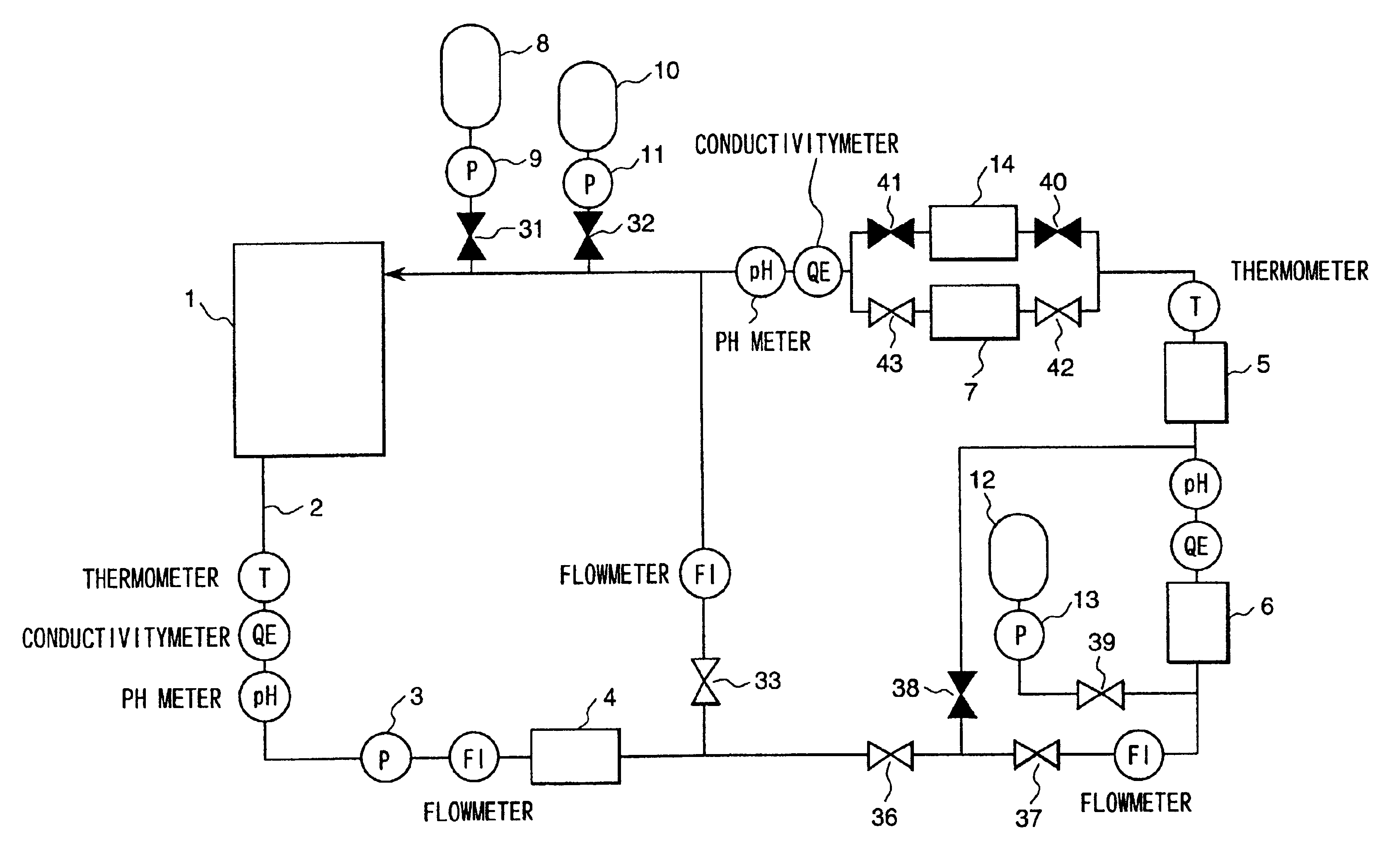
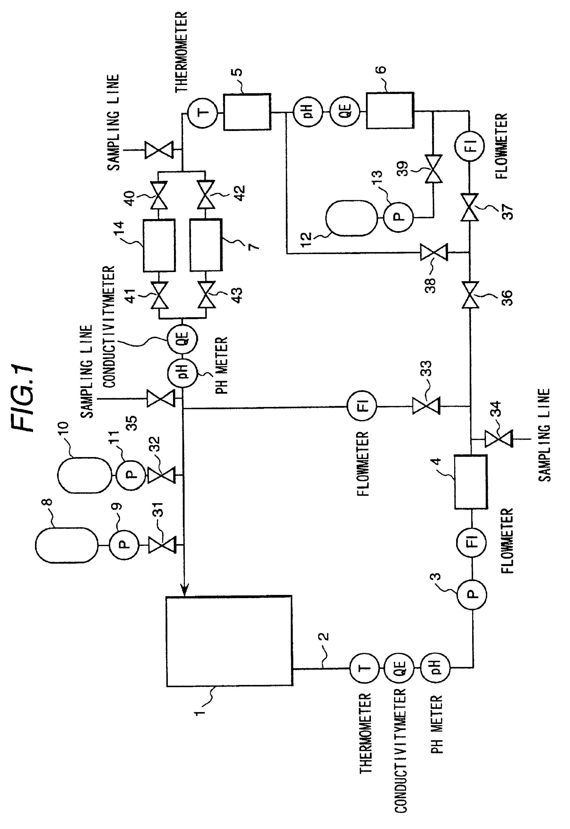
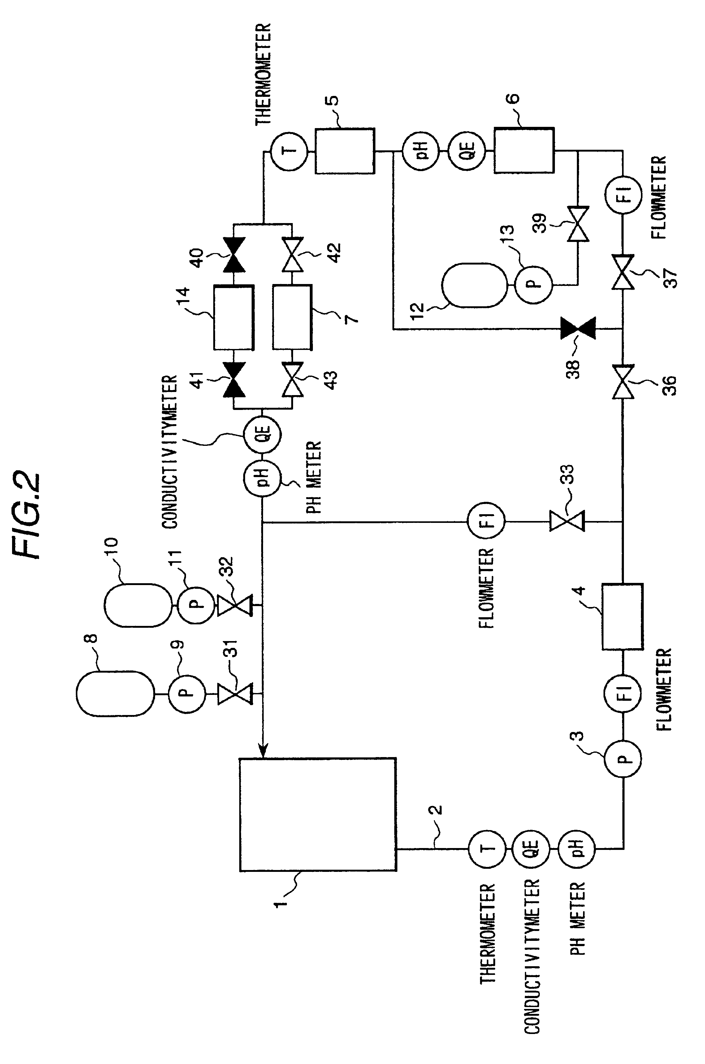
[0031]FIG. 1 is a diagram showing the basic system configuration of a chemical decontamination system to which an embodiment of a chemical decontamination method in accordance with the present invention is applied. Components used for performing decontamination are a circulation line 2 connected to a portion 1 to be decontaminated (pipes of a nuclear power plant and so on), a circulation pump 3, a heater 4, a cooler 5, a catalyst decomposition column 6, a cation resin column 7, an agent tank 8, an agent injection pump 9, a pH adjusting agent tank 10, a pH adjusting agent injection pump 11, a hydrogen peroxide tank 12, a hydrogen peroxide injection pump 13 and a mixed-bed resin column 14. Each of the above-described components and each valve to be described later are connected with a piping path.

[0032]FIG. 7(A) shows a main process of the present embodiment of a chemical decontamination method. The reducing treatment shown in FIG. 7 indicates decontamination using a red...

embodiment 2

[Embodiment 2]

[0055]Although in Embodiment 1 the vent mechanism is arranged in the catalyst decomposition column 6 in order to remove the produced gas, a gas-liquid separating tank having a vent cooler for separating the gas may be arranged downstream of the catalyst decomposition column 6 and upstream of the cation resin column 7. In this case, there is an advantage in that the gas-liquid separating tank 13 can be also used as a buffer for receiving a volume of liquid increased by injection of the agent.

embodiment 3

[Embodiment 3]

[0056]FIG. 9 is a diagram showing the basic system configuration of a chemical decontamination system to which a third embodiment of a chemical decontamination method in accordance with the present invention is applied.

[0057]The main process in the present embodiment of the chemical decontamination method is shown in FIG. 7(B). A different point of Embodiment 3 from Embodiment 1 (system configuration of FIG. 1) is that the position of the catalyst decomposition column 6 and the position of the cation resin column 7, the mixed-bed resin column 14 and the cooler 5 are in inverse order.

[0058]In Embodiment 3, the cooler 5, the cation resin column 7 and the mixed-bed resin column 14 are arranged in the upstream side of the catalyst decomposition column 6.

[0059]An advantage of the system configuration shown in Embodiment 3 is that the concentration of radioactivity in the water flowing to the catalyst decomposition column 6 is low because the water flows into the catalyst de...


PUM


Abstract

In a chemical decontamination apparatus, a catalyst decomposition column in an upstream side of an ion exchange resin column and a hydrogen peroxide injection apparatus in a further upstream side, reduce the amount of waste products caused by a chemical decontaminating agent where a mixed decontaminating agent for a composition trapped in a cation resin column and for a composition trapped in an anion exchange resin are used for the chemical decontaminating agent, selectively decompose the composition trapped in the cation resin column in an inlet side of a cleaning apparatus when radioactive nuclides in the decontaminating agent are cleansed using the cation resin column during decontamination, and decompose both compositions after completion of the decontamination. The chemical decontamination thus selectively decomposes the chemical decontaminating agent, which is a component of the load to the cation resin column.

Description

[0001]This is a divisional application of U.S. Ser. No. 09 / 405,217 filed Sep. 27, 1999, now U.S. Pat. No. 6,335,475.BACKGROUND OF THE INVENTION[0002]The present invention relates to a nuclear power plant of water cooling type and, more particularly, to a chemical decontamination method and a chemical decontamination system by which radioactive nuclides are chemically removed from metallic material surfaces of primary cooling system components and pipes and a system including the component and the pipes which are contaminated with radioactive nuclides.[0003]As conventional technologies in connection with chemical decontamination, Japanese Patent publication No.3-10919 discloses a method in which components of a nuclear power plant made of metals are chemically decontaminated using permanganic acid as an oxidizing agent and dicarboxylic acid as a reducing agent. As methods of decomposing the above-mentioned organic acids, PCT / JP97 / 510784 discloses a method of decomposing the acid into...

Claims


Application Information

Patent Timeline
IPC IPC(8): G21F9/00G21F9/28
CPCG21F9/004
Inventor NAGASE, MAKOTOUETAKE, NAOHITOISHIDA, KAZUSHIGENAKAMURA, FUMITOANAZAWA, KAZUMITAMAGAWA, TADASHIYOSHIKAWA, HIROO
Owner HITACHI-GE NUCLEAR ENERGY LTD
Features
  • Generate Ideas
  • Intellectual Property
  • Life Sciences
  • Materials
  • Tech Scout
  • Unparalleled Data Quality
  • Higher Quality Content
  • 60% Fewer Hallucinations
Learn More