Current driver and method of precisely controlling output current

Inactive Publication Date: 2005-07-26
MOBIX LABS INC +1
View PDF1 Cites 7 Cited by
  • Summary
  • Abstract
  • Description
  • Claims
  • Application Information

AI Technical Summary

Benefits of technology

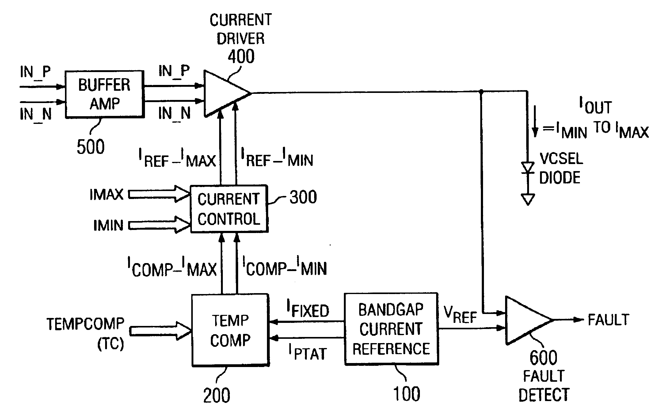
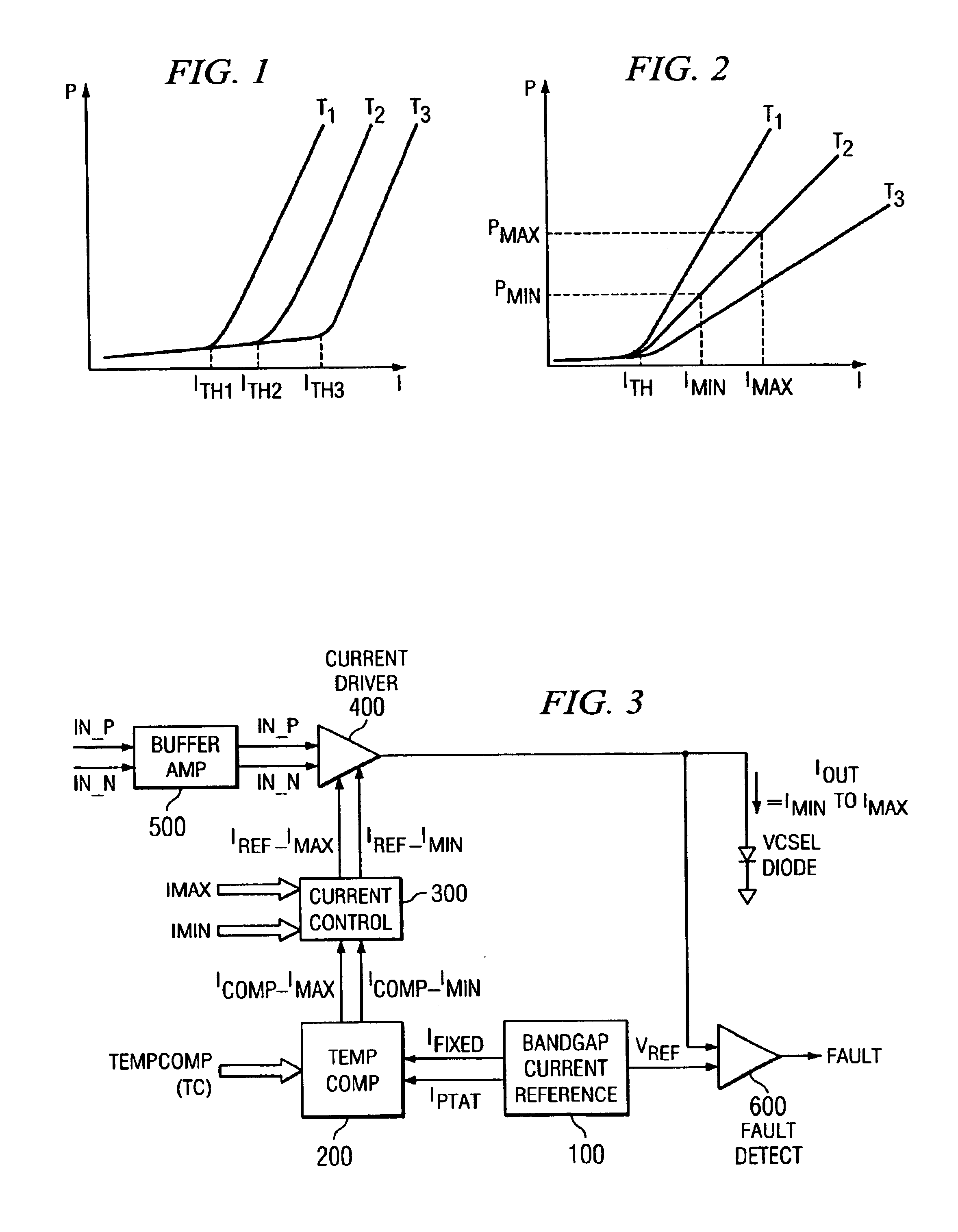
[0012]VCSEL diodes require current drive to modulate light output. The VCSEL driver described herein sources a programmable output current to the laser diode. The output current limits are programmed with control words (IMIN) for the minimum current and (IMAX) for the maximum current. Since the driver is a true current source, there is relative insensitivity to the load diode's characteristics. This allows for the use of various manufacturers' VCSELs without costly optical feedback mechanisms.
[0014]The current output operation of the VCSEL Driver also allows for a simple and efficient over voltage fault detection. With a known output modulation current, the output voltage varies significantly if the VCSEL diode or interconnects exhibit a high impedance condition. This output voltage can be sensed and compared to valid limits to determine a fault state.

Problems solved by technology

Since the driver is a true current source, there is relative insensitivity to the load diode's characteristics.

Method used


Image

  • Current driver and method of precisely controlling output current
  • Current driver and method of precisely controlling output current
  • Current driver and method of precisely controlling output current

Examples


Embodiment Construction

[0027]The present invention may be described herein in terms of various functional components and various processing steps. It should be appreciated that such functional components may be realized by any number of hardware or structural components configured to perform the specified functions. For example, the present invention may employ various integrated components comprised of various electrical devices, e.g., resistors, transistors, capacitors, diodes and the like, whose values may be suitably configured for various intended purposes. Further, it should be noted that while various components may be suitably coupled or connected to other components within exemplary circuits, such connections and couplings can be realized by direct connection between components, or by connection through other components and devices located therebetween. Also, for ease of explanation and understanding of the present invention, superfluous details have not been included.

[0028]Refer now to FIG. 1, w...


PUM


Abstract

Disclosed is current driver circuit comprising a bandgap reference circuit for generating a fixed current and a current proportional to absolute temperature (PTAT), a temperature compensator for combining the fixed and PTAT currents and forming first and second temperature compensated currents, a current control circuit for modifying said first and second temperature compensated currents in response to signals representing the characteristics of a load device and a driver circuit for amplifying and supplying a selected one of said first and second temperature compensated currents to said load device. Also disclosed is a method of supplying a precisely controlled current by generating a constant current and a current proportional to absolute temperature (PTAT), combining these two currents and providing temperature compensated currents, modifying the temperature compensated currents with a programmed reference signal and supplying a precisely controlled current to a load device.

Description

CROSS REFERENCE TO RELATED APPLICATIONS[0001]This patent application claims priority to, and the benefit of, U.S. provisional patent applications identified as follows:[0002]1. Provisional Application Ser. No. 60 / 356,806 entitled, Current Source Output Light Emitting Device Driver, filed Feb. 13, 2002.[0003]2. Provisional Application Ser. No. 60 / 407,496, entitled SYSTEM AND CIRCUIT FOR A MULTI-CHANNEL OPTOELECTRONIC DEVICE DRIVER Filed Aug. 30, 2002.[0004]3. Provisional Application Ser. No. 60 / 407,495 entitled SYSTEM AND CIRCUIT FOR AN OPTOELECTRONIC DEVICE DRIVER Filed Aug. 30, 2002;[0005]4. Provisional Application Ser. No. 60 / 407,493, entitled SYSTEM FOR TRANSMITTING OPTOELECTRONIC INFORMATION Filed Aug. 30, 2002.[0006]5. Provisional Application Ser. No. 60 / 407,494, entitled TRANSIMPEDANCE AMPLIFIER AND CIRCUIT INCLUDING THE SAME Filed Aug. 30, 2002.FIELD OF THE INVENTION[0007]The present invention generally relates to current driver circuits providing precisely controlled low lev...

Claims


Application Information

Patent Timeline
IPC IPC(8): G05F3/26G05F3/08G05F3/30H03F3/343H03F3/345
CPCG05F3/262G05F3/30H03F3/345H03F2203/45544H03F2203/45594H03F2203/45654Y10S323/907
Inventor SELF, DAVID W.MCCLAY, C. PHILLIP
Owner MOBIX LABS INC
Why Eureka
Try Eureka