
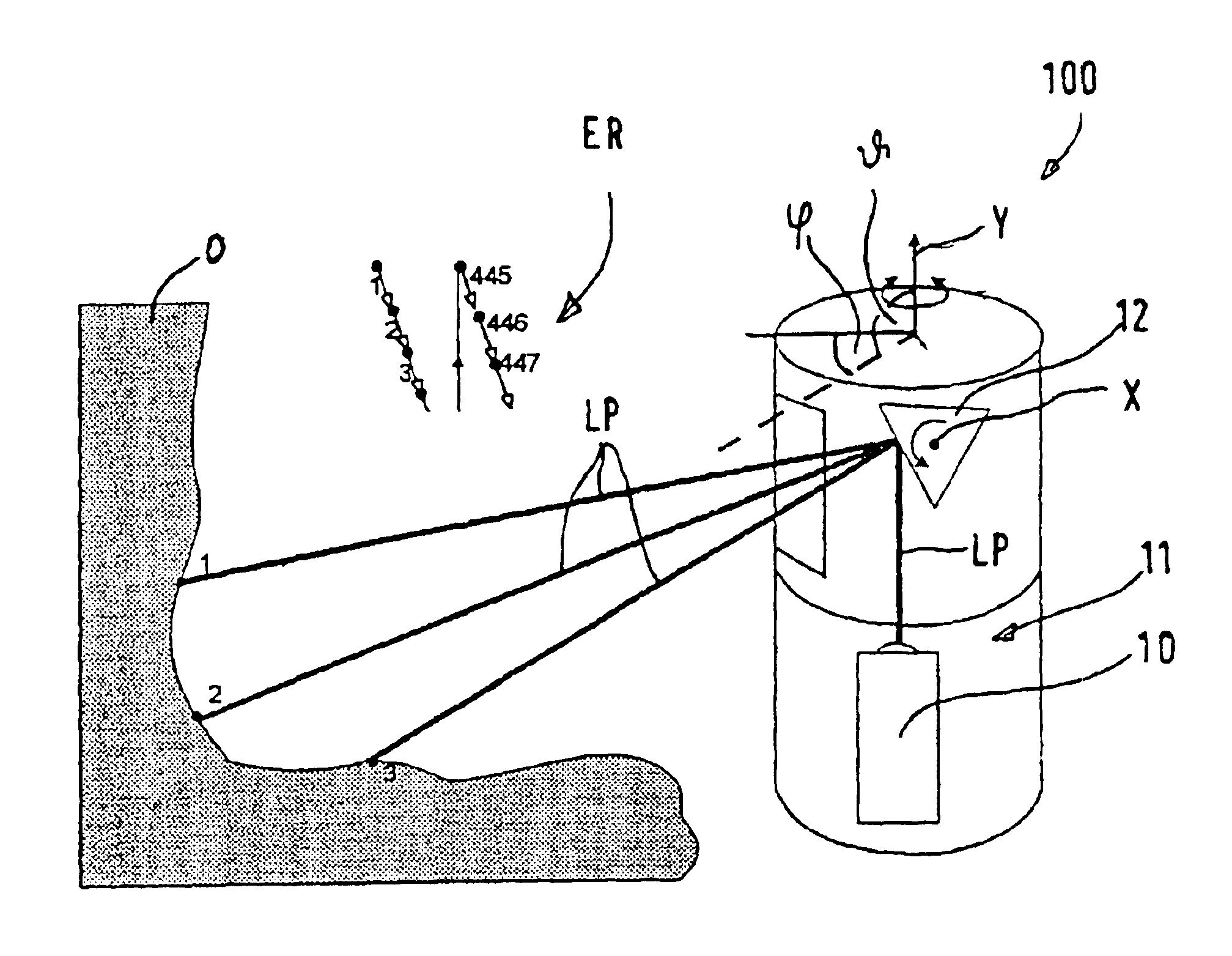
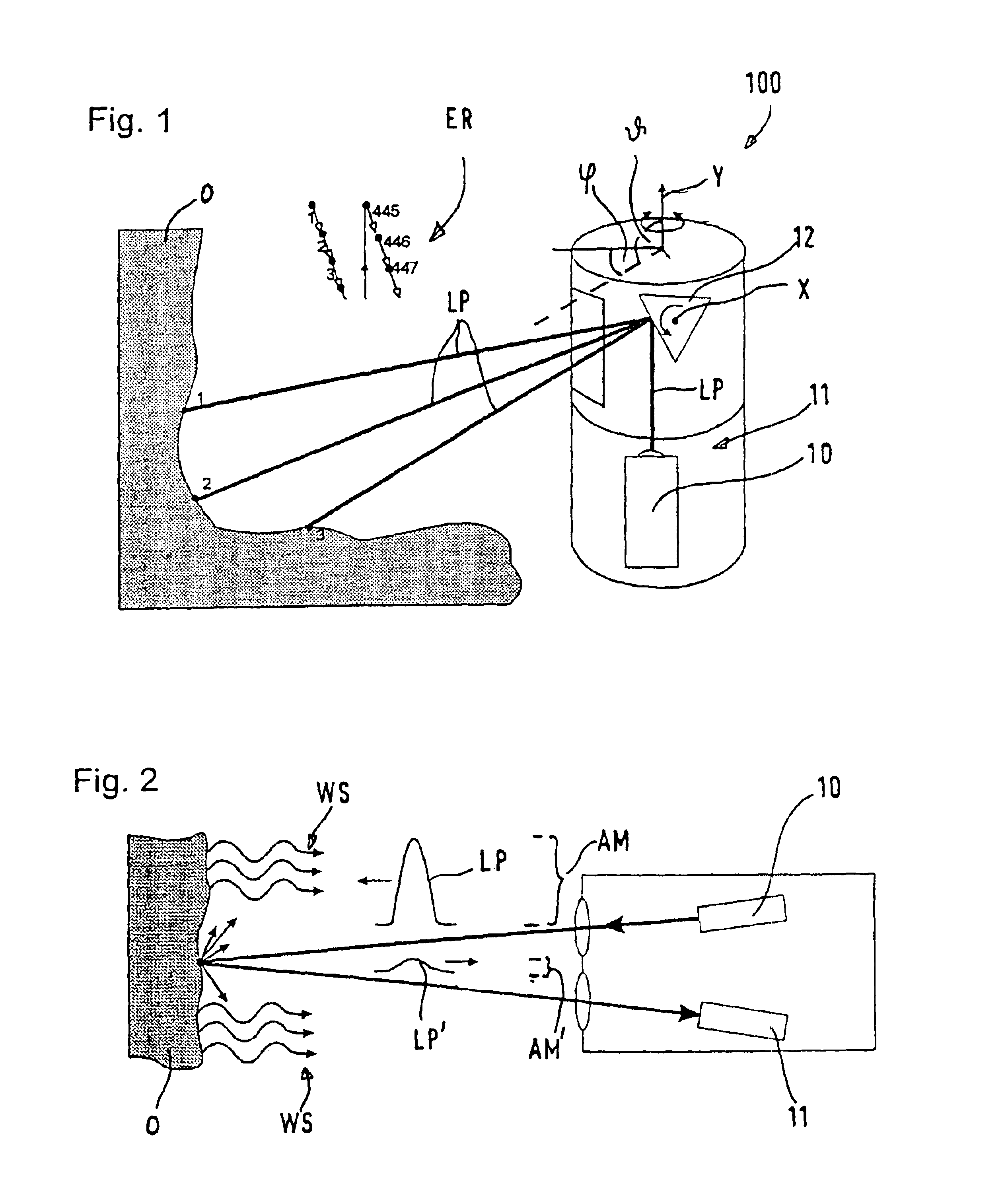
Measurement of the wear of the fireproof lining of a metallurgical vessel

a technology of fireproof lining and measurement method, which is applied in the direction of instruments, manufacturing converters, furniture, etc., can solve the problems of significant probability of error, inability to contact measurement, and limited measurement accuracy

Inactive Publication Date: 2005-07-26
SPECIALITY MINERALS (MICHIGAN) INC
View PDF14 Cites 44 Cited by
  • Summary
  • Abstract
  • Description
  • Claims
  • Application Information

AI Technical Summary

Benefits of technology

[0015]The object of the present invention is to create a method with which an object, in particular a metallurgical vessel, can be identified and have its position determined relative to an optical identification unit through recognition of a two- or three-dimensional structure that can comprise the vessel itself or a stationary construction with known geometry which has a defined relationship to the vessel, without the need for multiple measurements from different positions.

Problems solved by technology

For this reason, and also due to the inaccessibility of many metallurgical vessels, contacting measurement is inherently out of the question.
Although it has been demonstrated that the position and orientation of the vessel can be determined and also reconstructed before a subsequent wear measurement using this method, the method has the disadvantages that it is cumbersome because it is performed manually, and it has a significant probability of error.
While this method does in principle provide automation, it has the disadvantage that the achievable precision of measurement is limited both by the necessarily small size of the reference mark system and the resultant small displacement of individual points of the reference mark system when the vessel's position is changed, and by the merely two-dimensional position determination of the reference points.
Moreover, this method requires a separate, advance determination of the position of the vessel relative to the measurement device, which increases the amount of time needed for performing the wear measurement.
While this method has improved precision of measurement over that of DE 196 14 564 A1 because three-dimensional information is obtained by using the actual measurement equipment to determine the position of the reference points, it nevertheless has the disadvantage of requiring an advance reference measurement using the optical identification unit.
This method has the drawback that the positions must be known precisely relative to one another, which increases the measurement effort.

Method used


Image

  • Measurement of the wear of the fireproof lining of a metallurgical vessel
  • Measurement of the wear of the fireproof lining of a metallurgical vessel
  • Measurement of the wear of the fireproof lining of a metallurgical vessel

Examples


first embodiment

[0033]In the method in accordance with the invention, a sphere is used as the structure. It is especially suitable because the scalable structure of the operator depends on the distances alone, and not on the different angles of observation. The operator is defined by the known radius of the sphere and general sphere geometry. As the result coordinate, it is expedient to calculate the center point M of the sphere through addition of the known sphere radius p. This reference point coordinate is used together with other measured reference point coordinates to determine the position of the vessel in the device coordinate system.

[0034]In a second preferred embodiment of the method in accordance with the invention, a light-colored laminar mark that is recessed relative to its surroundings is used as the structure. The operator—hereinafter called “amplitude operator”—is first scaled using measured distance values Rad(m,n), and thus the expected size of the mark is calculated. The mark is ...

third embodiment

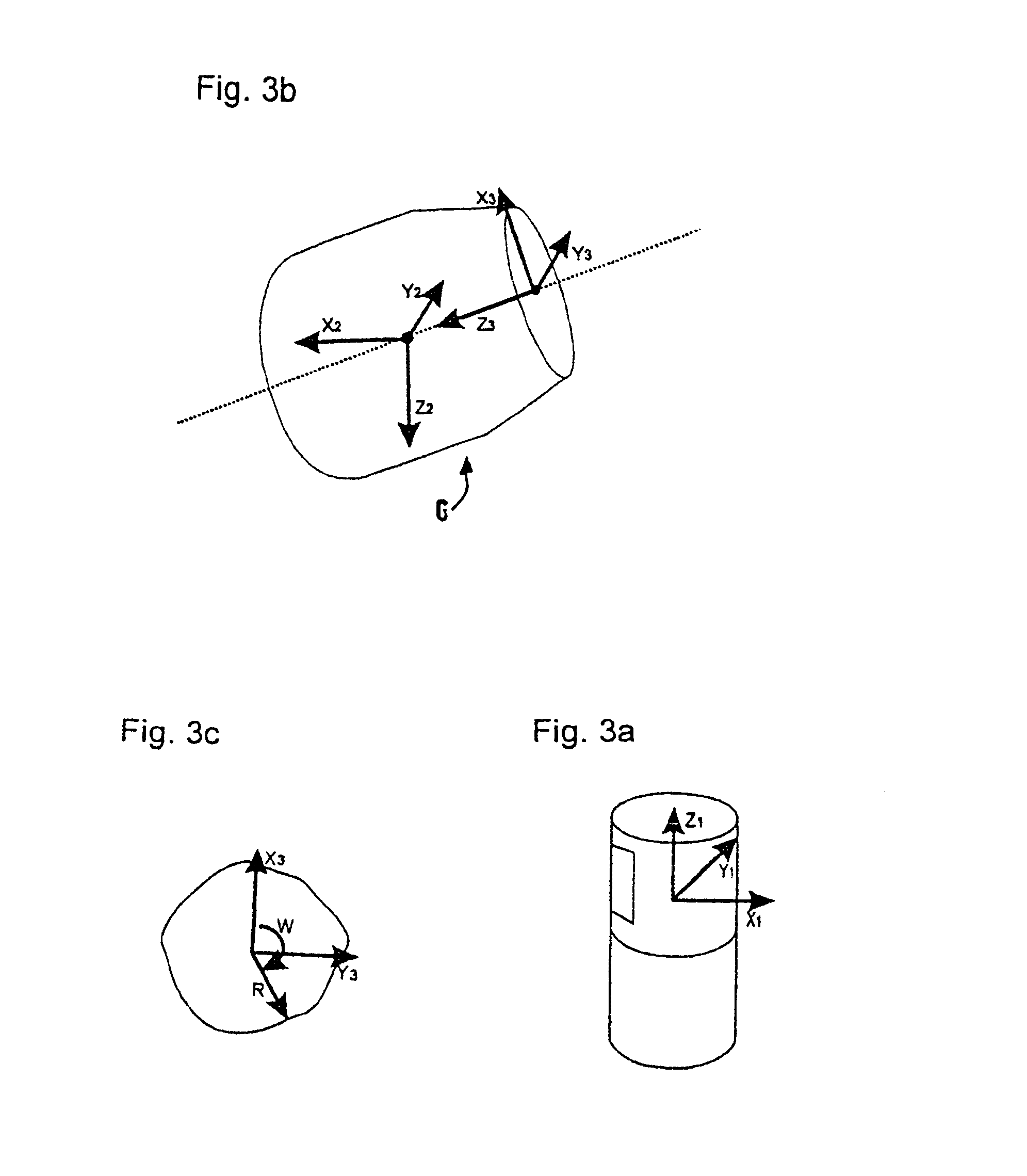
[0035]In the method in accordance with the invention, the vessel itself serves as the structure. This selection of structure is especially suitable for measurement of vessels having a fundamentally cylindrical structure. The operator—hereinafter called “V operator”—first finds a point on the vessel mouth, and from there calculates at least two additional points on the mouth of the vessel, where at least one point in the vessel interior is found as a control. In this embodiment of the method, the position and orientation of the vessel can be roughly determined even in a tilted state. This is necessary for subsequent calculations, for example precise calculation of the vessel's position preferably using the embodiment of the inventive method described below.

[0036]The subsequent embodiment of the method in accordance with the invention, which serves to calculate the precise position of the vessel, uses the vessel mouth as the structure. Using the rough positions found in the preceding ...


PUM

PropertyMeasurementUnit
Lengthaaaaaaaaaa
Thicknessaaaaaaaaaa
Angleaaaaaaaaaa

Abstract

According to the invention, a method for identifying and determining die position of a metallurgical vessel for measuring its fireproof lining using electromagnetic radiation, an operator is defined in relation to a two or three dimensional structure with a known shape and size. Distance values and corresponding measuring angles are determined in the area of the structure and measured distance value and corresponding measuring angles are used to scale the operator. The dimension and resolution of the operator in the pixel coordinates system and the anticipated values of the operator are adapted to the measured polar coordinates. A result value is then formed from the differences between the anticipated values of the operator and the measured values and the location of the structure that is sought is determined from the position of the minimum result value.

Description

FIELD OF INVENTION[0001]The invention relates to a method for the identification and determination of the position of an object, in particular a metallurgical vessel while measuring the wear of its refractory lining.BACKGROUND OF THE INVENTION[0002]To achieve increased effectiveness and improved reliability of the refractory linings of metallurgical vessels in steelworks, it is necessary to obtain as much information as possible about the wear of the linings during use (the so-called “campaign”) of the vessels.[0003]In this context, precise knowledge of the thickness of the refractory lining—also called “remaining refractory thickness”—is especially important, since it permits effective utilization of the refractory lining up to the wear limit without an increased risk of blowout of the metallic jacket of the metallurgical vessel.[0004]Consequently, efforts have been underway for quite some time to develop measurement methods that permit precise measurement of the metallurgical vess...

Claims


Application Information

Patent Timeline
IPC IPC(8): C21C5/44C21C5/46G01B11/02G01B11/24F27D21/00G01S17/89G01S17/00G01S7/48G01S7/487B22D2/00G01B11/00F27D1/00F27D1/16G01B11/03G01B21/00
CPCC21C5/44C21C5/4673F27D21/0021G01B11/026G01B11/24G01S7/4802G01S7/487G01S17/89G01S7/4817G01B11/02
Inventor KIRCHHOFF, STEFANCARLHOFF, CHRISTOFFLAMM, ROLF
Owner SPECIALITY MINERALS (MICHIGAN) INC
Learn More