
Flexible electro-optic displays

a technology of electro-optic displays and flexible elements, applied in the direction of liquid organic insulators, instruments, organic insulators, etc., can solve the problems of insufficient service life of these displays, preventing their widespread use, and being susceptible to mechanical damag

Inactive Publication Date: 2005-07-26
E INK CORPORATION
View PDF130 Cites 861 Cited by
  • Summary
  • Abstract
  • Description
  • Claims
  • Application Information

AI Technical Summary

Benefits of technology

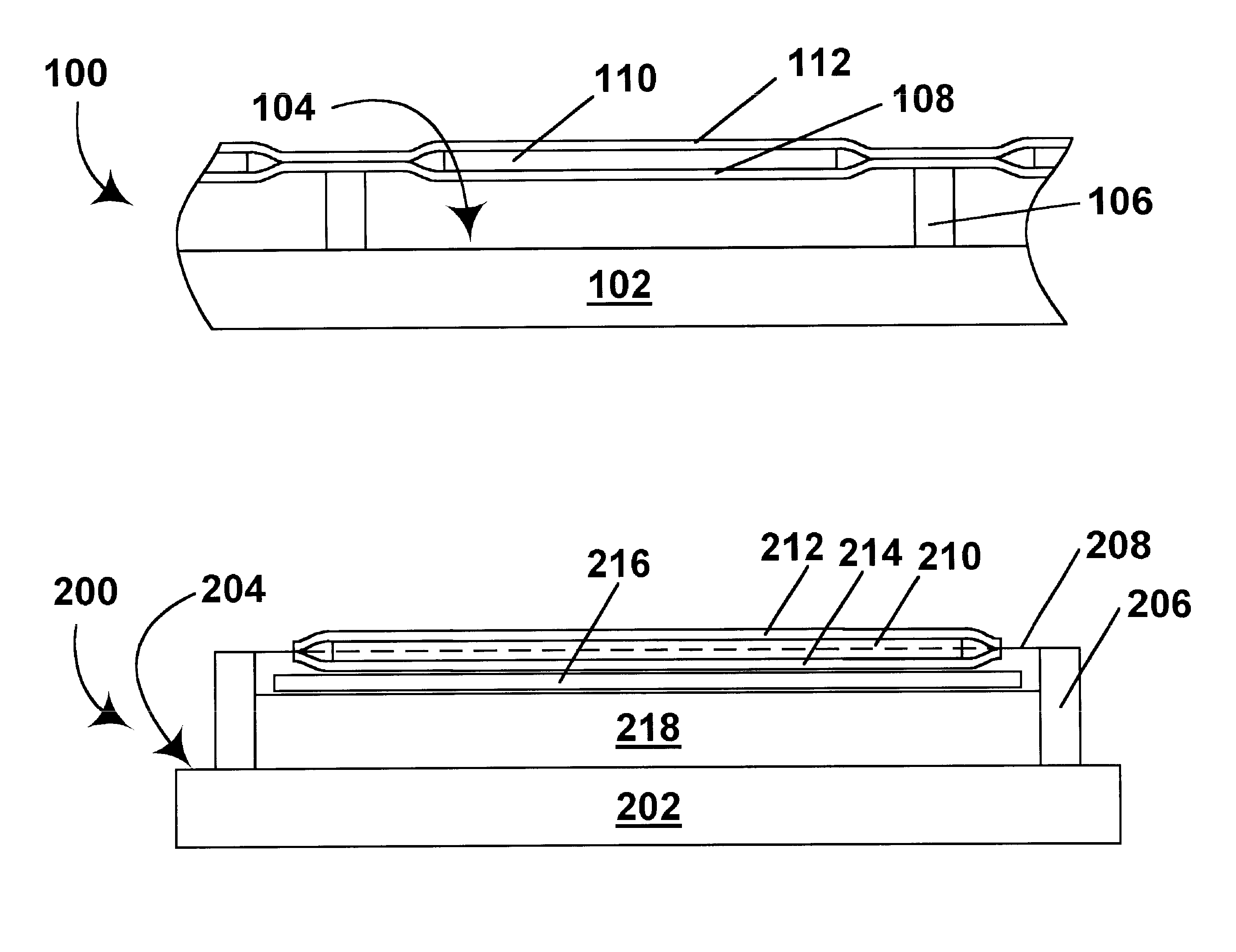
The high modulus binder and structural support systems significantly increase the resistance of encapsulated electrophoretic displays to mechanical damage, allowing for repeated bending without capsule bursting and improved durability, while the suspended and tensioned member designs further reduce susceptibility to stress concentrations.

Problems solved by technology

Nevertheless, problems with the long-term image quality of these displays have prevented their widespread usage.
For example, particles that make up electrophoretic displays tend to settle, resulting in inadequate service-life for these displays.
Although, as described above encapsulated electrophoretic media possess considerable strength and cohesion, they are still susceptible to mechanical damage during repeated bending or flexing of the display.
All such stylus-based displays are especially susceptible to mechanical damage because of the risk of a user exerting excessive pressure on the narrow tip of a stylus.
In addition, stylus-based displays cannot readily make use of the same type of front protective layer which can be used in displays with non-movable electrodes.
Thus, in a stylus-based display, the thickness of the front film is necessarily a compromise between the need for as large a field as possible across the electro-optic medium and the need for protection of the medium, and in practice such stylus-based displays tend to have thinner front films than displays using fixed electrodes, and hence to be more susceptible to mechanical damage.

Method used


Image

  • Flexible electro-optic displays
  • Flexible electro-optic displays

Examples


example 1 (

CONTROL)

[0029]Encapsulated dual particle electrophoretic displays were prepared substantially as described in Examples 27-29 of the aforementioned 2002 / 0185378, except that the binder used was pure NeoRez R 9320, available from NeoResins, 730 Main Street, Wilmington, Mass. 01887 (“NEOREZ” is a Registered Trade Mark). R 9320 is a non-ionically stabilized polyester-based water-dispersed urethane adhesive, and is a soft material with a shear modulus of approximately 1 mPa at 20° C. and relatively poor adhesion to ITO-coated PET, as shown by a peel strength (determined by hot laminating the adhesive between two sheets of ITO-coated PET and peeling on PET back at a 180° angle) of less than 1 lb / inch (less than about 0.2 kg / cm).

[0030]Wrapping the displays thus prepared around a 1 inch (25 mm) mandrel for 24 hours resulted in significant capsule bursting. The samples also showed significant capsule damage after 5-6 successive bends around the same mandrel. Finally, the compressive strength...

example 2

[0031]Encapsulated dual particle electrophoretic displays were prepared in the same way as in Example 1 except that the binder used was a 1:1 w / w blend of NeoRez 9621 and NeoRez 9314; both these materials are water-dispersed polyurethane adhesives from the same supplier as the NeoRez 9320 mentioned above. The resultant binder has a shear modulus of approximately 100 mPa and an adhesion (measured in the same manner as in Example 1) of more than 4 lb / inch (more than about 0.7 kg / cm).

[0032]Wrapping the displays thus prepared around a 1 inch (25 mm) mandrel for two weeks resulted in no measurable capsule bursting. In addition, only minor capsule damage was observed after 100 successive bends around the same mandrel. Finally, the compressive strength of the capsules (measured in the same manner as in Example 1) was greater than 1100 g.

[0033]In addition to the high modulus binder aspect of the invention, the present invention provides several other improvements relating to improving the r...


PUM

PropertyMeasurementUnit
shear modulusaaaaaaaaaa

Abstract

An encapsulated electrophoretic medium comprises a plurality of capsules dispersed in a polymeric binder, each of the capsules comprising a capsule wall, a suspending fluid contained within the capsule wall, and a plurality of electrically charged particles suspended in the suspending fluid and capable of moving therethrough upon application of an electric field to the medium, the polymeric binder having a shear modulus of at least about 10 mPa at 20° C., and preferably over the range of 10-50° C.

Description

CROSS REFERENCE TO RELATED APPLICATIONS[0001]This application claims benefit of copending Application Ser. No. 60 / 319,809, filed Dec. 23, 2002. The entire disclosure of this copending application is herein incorporated by reference. The entire disclosures of all U.S. patents and published and copending applications referred to below are also herein incorporated by reference.BACKGROUND OF INVENTION[0002]This invention relates to flexible electro-optic displays and processes for the production of such displays. This invention is especially but not exclusively intended for use with encapsulated electrophoretic displays.[0003]The term “electro-optic” as applied to a material or a display, is used herein in its conventional meaning in the imaging art to refer to a material having first and second display states differing in at least one optical property, the material being changed from its first to its second display state by application of an electric field to the material. Although the...

Claims


Application Information

Patent Timeline
Patent Type & Authority Patents(United States)
IPC IPC(8): G09G3/34H01B3/20H01B3/18G02F1/167G02F1/1679
CPCG02F1/167G02F1/1679
Inventor ZHANG, LIBINGHOLMAN, MAVYN M.WILCOX, RUSSELL J.GOENAGA, ALBERTOSTEINER, MICHAEL L.
Owner E INK CORPORATION
Learn More