Harmonic generation microscopy

a technology of harmonic generation and microscopy, applied in the field of harmonic generation microscopy, can solve the problems of inducing affecting the image quality of observed samples, and toxic in vivo samples of fluorescent dyes, and achieve the effect of removing photo-damage to observed samples

Active Publication Date: 2005-07-26
NARIONAL TAIWAN UNIV
View PDF5 Cites 31 Cited by
  • Summary
  • Abstract
  • Description
  • Claims
  • Application Information

AI Technical Summary

Benefits of technology

[0011]Therefore, a primary object of the present invention is to provide a harmonic generation microscopy that eliminates photo-damage to the observed samples.
[0012]Another object of the present invention is to provide a harmonic generation microscopy that uses both second harmonic generation and third harmonic generation at the same time to provide a clear image comprising both a continuous noncentrosymmetric structure and an interface of the structure.

Problems solved by technology

However, the fluorescent dye may be toxic to in vivo samples.
Further, the excitation of the fluorescent light by absorption of photons may induce photo-damages to the observed samples.
For example, with a Ti: Sapphire laser having a pulse duration 100 fs and a repetition rate of 80 MHz, an average power exceeding 6 mW causes photo-damage to the samples.
However, SHG is not suitable for the observation of interfaces in biological samples.
Since THG often occurs in the interface, THG is not suitable for observation of bulk noncentrosymmetric media, which, however, can be clearly inspected by means of SHG.
Due to the generation of the fluorescent light, photo-damage is inherent in this technique.
Further, due to lacking of the second harmonic wave, noncentrosymmetric object cannot be well examined by this technique.
Apparently, the conventional microscopic imaging techniques discussed above have one or more drawbacks in providing clear and wide range observation of a sample.

Method used


Image

  • Harmonic generation microscopy
  • Harmonic generation microscopy
  • Harmonic generation microscopy

Examples


Embodiment Construction

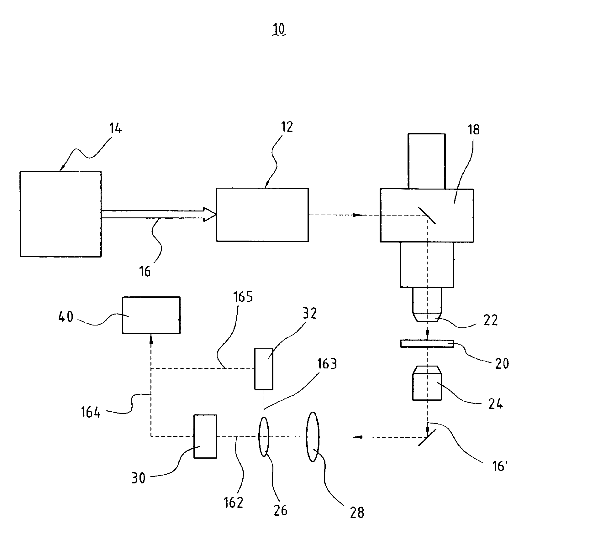
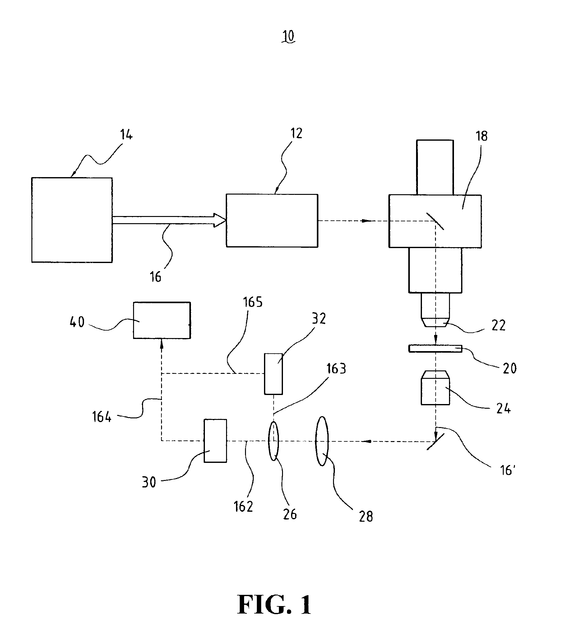
[0018]With reference to the drawings and in particular to FIG. 1, a microscopic imaging system in accordance with the present invention, generally designated with reference numeral 10, comprises a scanning device 12 that receives a laser beam 16 from a laser device or laser source 14, such as a short pulse laser device. Optic elements, such as a mirror array (not shown) capable of two-dimensional rotation, are included in the scanning device 12 for directing the laser beam 16 into a microscope 18.

[0019]A sample 20 to be observed is positioned in the microscope 18. The sample can be any suitable ones, such as a biological sample on a glass plate. This in known to those having ordinary skills in the field of biology and thus no further detail is needed herein.

[0020]The laser beam 16 that is directed into the microscope 18 by the scanning device 12 is focused by an objective lens 22 of the microscope 18 onto the sample 20, which induces an observation beam 16′ by letting the laser beam...


PUM

PropertyMeasurementUnit
wavelengthaaaaaaaaaa

Abstract

A harmonic generation microscopy employs a laser device that emits a laser beam having a predetermined wavelength that causes no autofluorescence in a biological sample and that, after excited, induces both the second and third harmonic waves. The laser beam is projected onto a sample and an observation beam from the sample is received. The observation beam is directed through a splitter to separate the second harmonic wave and the third harmonic wave both of which are then converted into corresponding electrical signals. The electrical signals are fed to a computer-based image processing equipment to form an image of the sample on the basis of the second and third harmonic waves.

Description

BACKGROUND OF THE INVENTION[0001]1. Field of the Invention[0002]The present invention relates generally to the field of harmonic generation microscopy, and in particular to a microscopic imaging technique using both second and third harmonic waves of a excitation spectrum of a laser beam by a sample to form an image of the sample.[0003]2. The Related Art[0004]Microscopic imaging has been widely used in a variety of applications. For example, microscopic observation of a biological tissue is one of the best-known applications of the microscopic imaging techniques. The recent development of the microscopic imaging allows for the employment of laser beam in high precision observation of biological samples. An example of the laser-based microscopy is two-photon laser scanning fluorescent microscopy that was published in Science, New Series, Volume 248, Issue 4951 (Apr. 6, 1990), pp 73-76, by Winfried Denk, James H. Strickler and Watt W. Webb. A biological sample is stained by a fluoresc...

Claims


Application Information

Patent Timeline
Patent Type & Authority Patents(United States)
IPC IPC(8): G01N21/64G01N21/63G02B21/06G02B21/36
CPCG01N21/636G02B21/06G02B21/365
Inventor SUN, CHI-KUANGCHU, SHI-WEI
Owner NARIONAL TAIWAN UNIV
Why Eureka
Try Eureka