Method and apparatus to reduce variation of excess fiber length in buffer tubes of fiber optic cables

Inactive Publication Date: 2005-07-26
ALCATEL LUCENT SAS
View PDF28 Cites 147 Cited by
  • Summary
  • Abstract
  • Description
  • Claims
  • Application Information

AI Technical Summary

Benefits of technology

[0018]It is to be noted that it is further contemplated that although the above embodiments can be used individually to obtain a substantially even EFL distribution, it is contemplated that any combination of the embodiments, or components thereof, can be used without altering the scope o

Problems solved by technology

However, when reeling of the buffer tubes occurs with constant tensile draw on the tubes and constant angular speed of the spool the result is non-uniform distribution of residual stresses along the length of the buffer tube as it sits on the spool.
In some cases, the non-uniform distribution of EFL remains after taking the tube off the spool and subsequently negatively affecting attenuation in the finished cable.
It is noted that this problem not only exists in the fiber optic industry, but also in any other industry where the extended rolling of a product is required.
For example, the same problems exist in the manufacture of paper, electrical cable, aluminum sheet, etc.
The creation of residual strain in the fibers is a very serious problem in the manufacture of fiber optic cables and buffer tubes that causes variation of EFL along the length of the tubes and subseq

Method used


Image

  • Method and apparatus to reduce variation of excess fiber length in buffer tubes of fiber optic cables
  • Method and apparatus to reduce variation of excess fiber length in buffer tubes of fiber optic cables
  • Method and apparatus to reduce variation of excess fiber length in buffer tubes of fiber optic cables

Examples


second embodiment

[0155]Also, as discovered in the present invention, variations in the line speed and the corresponding variation in angular velocity (“ω”) of the reel produce a variation in temperature and tensile load through the radius of the buffer tube roll. In this embodiment, a monotonically variable angular velocity of the spool is used to control the stress state in the buffer tubes, and subsequently the EFL distribution. It should be noted that it is preferred to use the monotonically variable angular velocity of the spool of this embodiment with a stiffness-compliant pad on the reel core to achieve a substantially even EFL distribution. This will be discussed in more detail below.

[0156]Examples of two possible monotonically variable curves for the angular speed of the spool are shown in FIG. 10. The curves shown 103 and 104 represent two out of many possible monotonically variable curves for angular velocity. It is noted that the exact shape of the monotonically variable curves will depen...

first embodiment

[0228]In the present invention, the take-up tension of the buffer tube is monotonically decayed as the tube is wound on the reel. The exact function used to decay the tension would be governed by the individual characteristics of the manufacturing system to be used, but is to be optimized by taking into account all of the factors previously discussed, including, line speed, reel core diameter, material properties, etc. Although it is preferred that a monotonically decaying function be used, it is contemplated that other functions may also be used to decay the tensile load on the tube during manufacture, without expanding the scope or spirit of the present invention. Further, although one of the main purposes of the present invention is to create uniform EFL distribution throughout the length of a buffer tube, it is contemplated that the present invention can be used to create a controlled non-uniform EFL distribution throughout the length of the cable, where such a non-uniform distr...

third embodiment

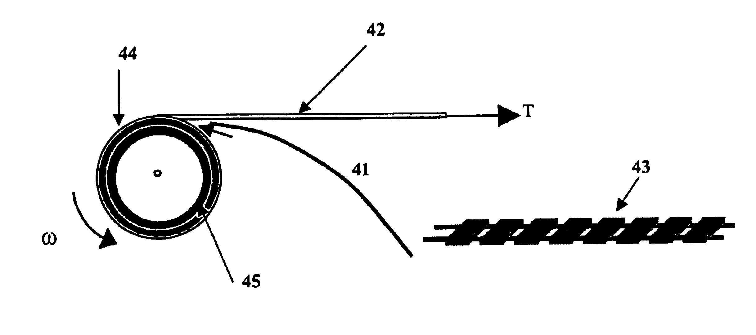
[0236]In the present invention, soft-cushion pads are inserted periodically with the tubes during the reeling process. This is depicted in FIG. 40 where a pad 41 is periodically inserted in the winding of the tube 42. It is preferred that the pad 41 be the width of the spool 44 and a length equal to the spool circumference at the point of insertion. It is also preferred that the pad be of a material, such as foam sheets, which would accommodate shrinkage in the tube as it cools on the reel 44. It should be noted that as an alternative to using periodically inserted pads 41, it is contemplated that a continuous pad be fed with the buffer tube 42 onto the reel 44 so that a cushioning layer is provided continuously throughout the reeled buffer tube 42. It is further contemplated that a core pad 45, as previously described above, can also be used in this embodiment.

[0237]The use of the periodic insertion of pads 41 according to the present embodiment provides space to accommodate shrink...


PUM


Abstract

The present invention provides a method for reducing and/or controlling the variations of excess fiber length along the length of reeled fiber optic buffer tubes during the manufacture of the buffer tubes. The present invention varies any number, or combination, of parameters during the manufacture of buffer tubes to achieve a substantially uniform excess fiber length along a reeled buffer tube. One embodiment of the inventive method uses monotonically decaying draw or take-up tension of the buffer tubes during winding, combined with a stiffness-compliant pad placed on the reel core to aid in providing a substantially uniform excess fiber length in the tube, while another embodiment uses a monotonically increasing angular speed of the reel in combination with the stiffness-compliant pad on the reel core. In yet another embodiment a pad is placed either periodically or continuously in the windings of the buffer tube to provide an absorbing layer for the residual stresses existing in the buffer tube as it is reeled and after the reeling is complete, combined with re-reeling the buffer tube onto a second reel after the buffer tube has cooled (after manufacture), where the pad is removed during the re-reeling process. Additionally, the present invention can have the layers of buffer tube separated with rigid, cylindrical panels separating the layers. The present inventive method also combines any, or all, of the above steps to aid in achieving a substantially uniform excess fiber length along the length of the reeled buffer tube.

Description

[0001]This application claims benefit of U.S. Provisional Application No. 60 / 256,454 filed on Dec. 20, 2000, under the provisions of 35 USC 119(e).BACKGROUND OF THE INVENTION[0002]1. Field of the Invention[0003]The present invention generally relates to the field of optical fibers, in particular to the manufacture of fiber optic buffer tubes having a substantially constant excess fiber length (“EFL”) ratio throughout the length of the buffer tube.[0004]2. Discussion of Related Art[0005]Optical fibers are very small diameter glass strands which are capable of transmitting an optical signal over great distances, at high speeds, and with relatively low signal loss as compared to standard wire or cable (including wire cable) networks. The use of optical fibers in today's technology has developed into many widespread areas, such as: medicine, aviation, communications, etc. Most applications of optical fibers require the individual fibers to be placed into groupings, such as in fiber opti...

Claims


Application Information

Patent Timeline
IPC IPC(8): B65H55/00B65H55/04B65H75/18G02B6/44
CPCB65H55/04B65H75/18G02B6/4484B65H2701/32B65H2701/331B65H2701/3916B65H2701/514G02B6/4457
Inventor NECHITAILO, NICHOLAS V.RATTAZZI, DEAN J.SOLTIS, MATTHEWROSSI, MICHAEL
Owner ALCATEL LUCENT SAS
Why Eureka
Try Eureka