Process cartridge and electrophotographic image forming apparatus having electrical connection for memory

a technology of electrophotographic image and process cartridge, which is applied in the direction of electrographic process apparatus, instruments, optics, etc., can solve the problem of irregular electrical contact pressur

Inactive Publication Date: 2005-07-26
CANON KK
View PDF29 Cites 62 Cited by
  • Summary
  • Abstract
  • Description
  • Claims
  • Application Information

AI Technical Summary

Benefits of technology

[0012]An object of the present invention is to provide a process cartridge and an electrophotographic image forming apparatus in which a main body electrical contact provided on an apparatus

Problems solved by technology

For this reason, in a state in which a driving force is applied and not applied, there was a possibility of causi

Method used


Image

  • Process cartridge and electrophotographic image forming apparatus having electrical connection for memory
  • Process cartridge and electrophotographic image forming apparatus having electrical connection for memory
  • Process cartridge and electrophotographic image forming apparatus having electrical connection for memory

Examples


first embodiment

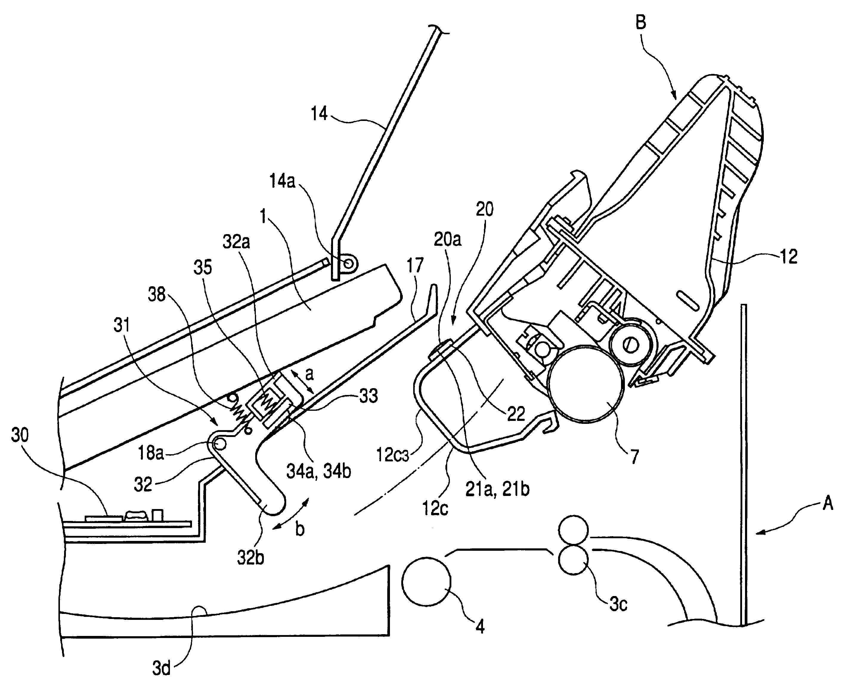
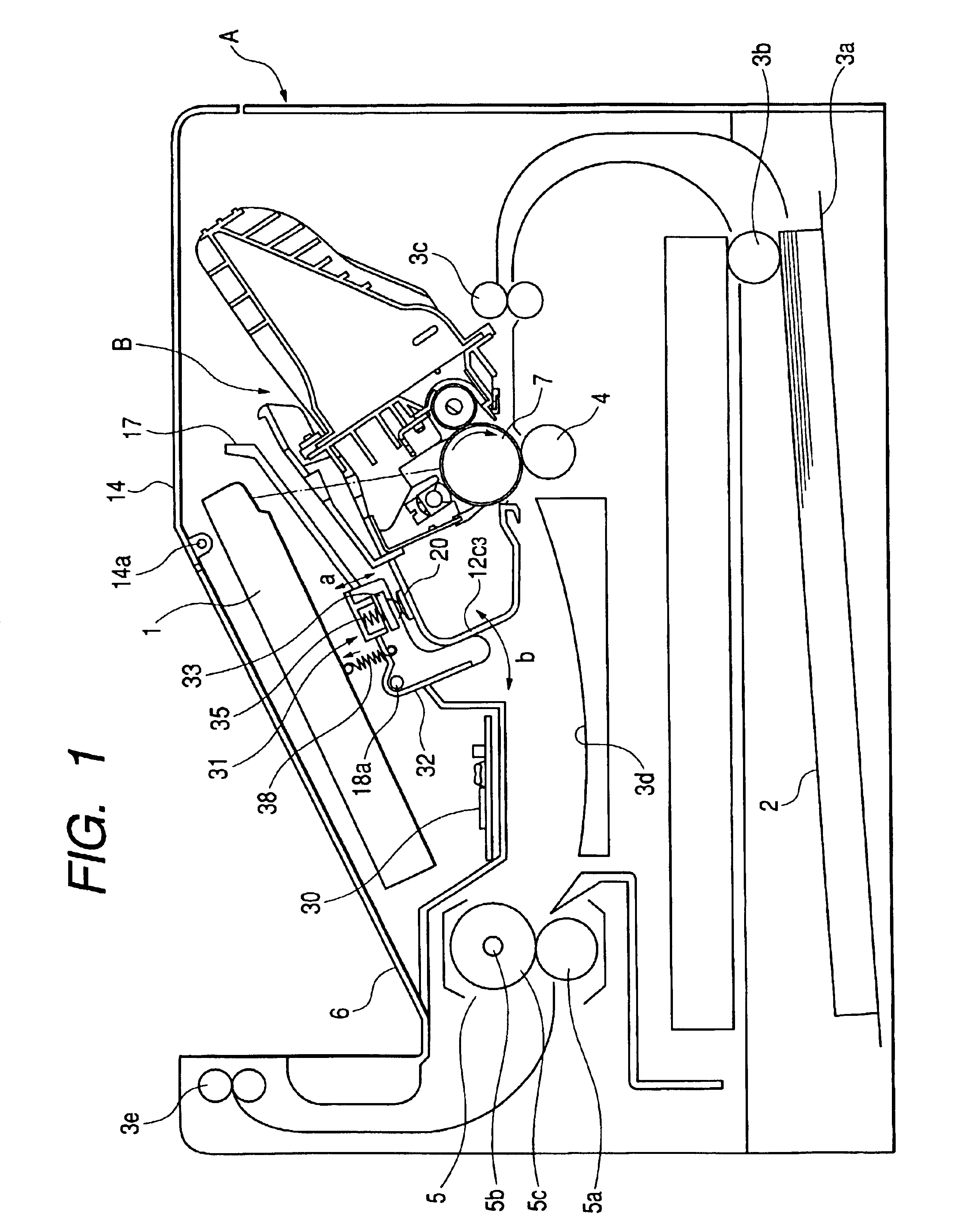
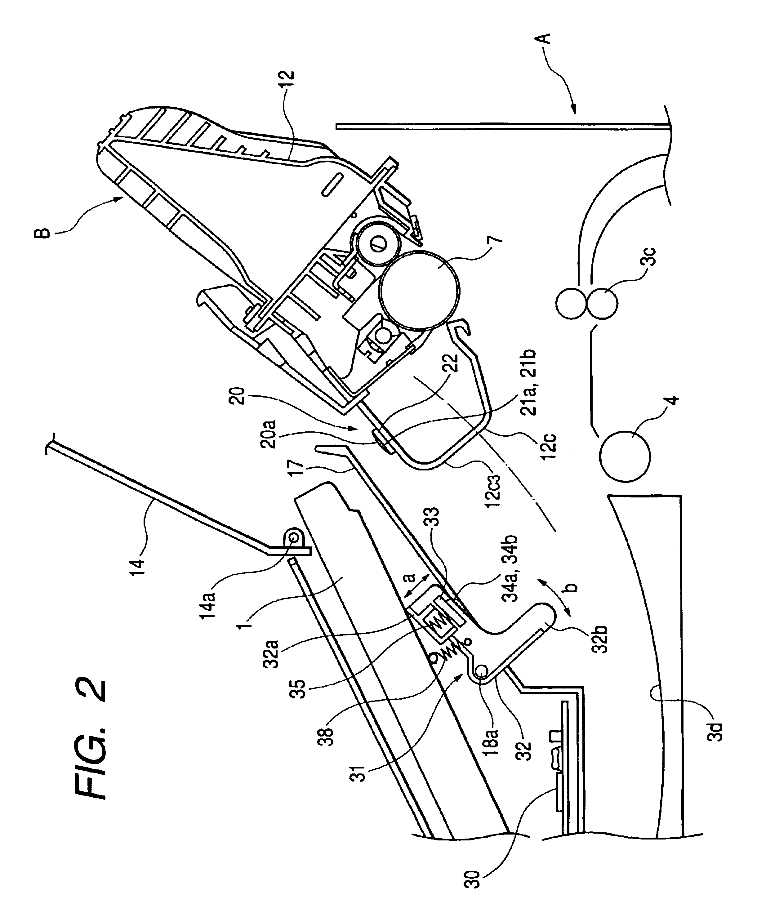
[0092]A process cartridge and an electrophotographic image forming apparatus detachably attachable with the process cartridge which are constituted based on the present invention, and subsequently, storage means as a main board of the process cartridge and electrical connecting means of an apparatus main body side will be described with reference to FIG. 1 to FIG. 7. Hereinafter, in the present embodiment, a description will be provided by taking an electrophotographic laser beam printer as an example.

[0093]An image forming apparatus A, as shown in FIG. 1, forms a latent image on the photosensitive body drum by irradiating a cylindrical electrophotographic photosensitive body 7 (hereinafter, referred to simply as a photosensitive body drum) with a laser beam image based on image formation from an optical system (scanner), and develops this latent image to form a developer image by using the developer.

[0094]Synchronizing with the formation of the developer image, a recording medium 2...

second embodiment

[0124]Next, a second embodiment of the image forming apparatus of the present invention will be described by using FIG. 8 and FIG. 9. The present embodiment is different from the first embodiment in the constitution of the electrical connecting means of the apparatus main body side which is electrically connected with the storage means. Here, only the points that are different from the first embodiment, will be described, and the other points will be omitted. Note that the description will be provided by giving the same reference symbols to the same members as those of the first embodiment.

[0125]Electrical connecting means 41 in the present embodiment, as shown in FIG. 8 and FIG. 9, is constituted by a rotary arm 42 which is a first movable member formed almost in the shape of L character and a contact holder 43 which is a second movable member. This electrical connecting means 41 is arranged at a position opposing to the storage means 20 when the process cartridge B is loaded on th...

third embodiment

[0136]Next, a third embodiment of the image forming apparatus of the present invention will be described by using FIG. 10 and FIG. 11. The present embodiment is different from the first and the second embodiments in the constitution of electrical connecting means of the apparatus main body to be electrically connected with storage means. Here, only the points that are different from the first and the second embodiments, will be described, and the other points will be omitted. Note that the description will be provided by giving the same reference symbols to the same members as those of the first and the second embodiments.

[0137]Electrical connecting means 51 in the present embodiment, as shown in FIG. 10 and FIG. 11, is arranged at a position opposing to the storage means 20 when a process cartridge B is attached onto an apparatus main body A. This electrical connection means 51 has an almost L-shaped rotary arm 52, and this rotary arm 52 is formed by a main body portion 52a, into w...


PUM


Abstract

A process cartridge includes a frame body, a substrate having a memory element, and a cartridge electrical contact and a cartridge pushing portion provided on the frame body. An electrophotographic image forming apparatus on which the process cartridge is loaded includes a main body electrical connector and main body electrical contacts. The cartridge pushing portion moves the main body electrical connector so that the process cartridge moves in a direction to be electrically connected with the cartridge electrical contact when the process cartridge is loaded on the electrophotographic image forming apparatus. The cartridge pushing portion operates so as to give a pushing force for pushing the main body electrical contact in a direction to be electrically connected with the cartridge electrical contact. In this way, the main body electrical contact and the cartridge electrical contact can be stably reliably brought into contact.

Description

BACKGROUND OF THE INVENTION[0001]1. Field of the Invention[0002]The present invention relates to a process cartridge and an electrophotographic image forming apparatus detachably attachable with the process cartridge.[0003]2. Related Background Art[0004]Examples of an electrophotographic image forming apparatus includes, for example, an electrophotographic copying machine, an electrophotographic printer (for example, a LED printer, a laser printer and the like), an electrophotographic facsimile, an electrophotographic word processor and the like.[0005]Further, the process cartridge includes an electrophotographic photosensitive body and at least one of charging means, developing means and cleaning means that are integrally turned into a cartridge as process means so as to be detachably attachable with an electrophotographic image forming apparatus main body. Or, furthermore, at least developing means and the electrophotographic photosensitive body are integrally turned into a cartri...

Claims


Application Information

Patent Timeline
IPC IPC(8): G03G21/18
CPCG03G21/1871G03G21/1885G03G2221/166G03G2221/1823
Inventor GOTO, HIROSHIMIURA, SEIETSUTAMURA, NOBUYAIBARAKI, YOSHIHISAMIYAZAKI, YOSHIYUKIMAEDA, MASAFUMITANOUE, MASAHIDENONAKA, FUMITO
Owner CANON KK
Why Eureka
Try Eureka