Method for modelling flows in a fractured medium crossed by large fractures

a fluid flow and fracture technology, applied in the field of method for modelling can solve the problems of difficult implementation of previous techniques, and inability to model fluid flow in a fractured medium

Inactive Publication Date: 2005-07-26
INST FR DU PETROLE
View PDF6 Cites 30 Cited by
  • Summary
  • Abstract
  • Description
  • Claims
  • Application Information

AI Technical Summary

Benefits of technology

[0019]The present invention allows precise simulation of flows

Problems solved by technology

There are cases where the previous techniques are difficult to implement, in the presence of an medium crossed by large fractures or sub-seismic faults whose hydraulic behavior cannot be homogenized on the scale of the cell.
Explicit modelling of these objects is therefore necessary a pr

Method used


Image

  • Method for modelling flows in a fractured medium crossed by large fractures
  • Method for modelling flows in a fractured medium crossed by large fractures
  • Method for modelling flows in a fractured medium crossed by large fractures

Examples


Embodiment Construction

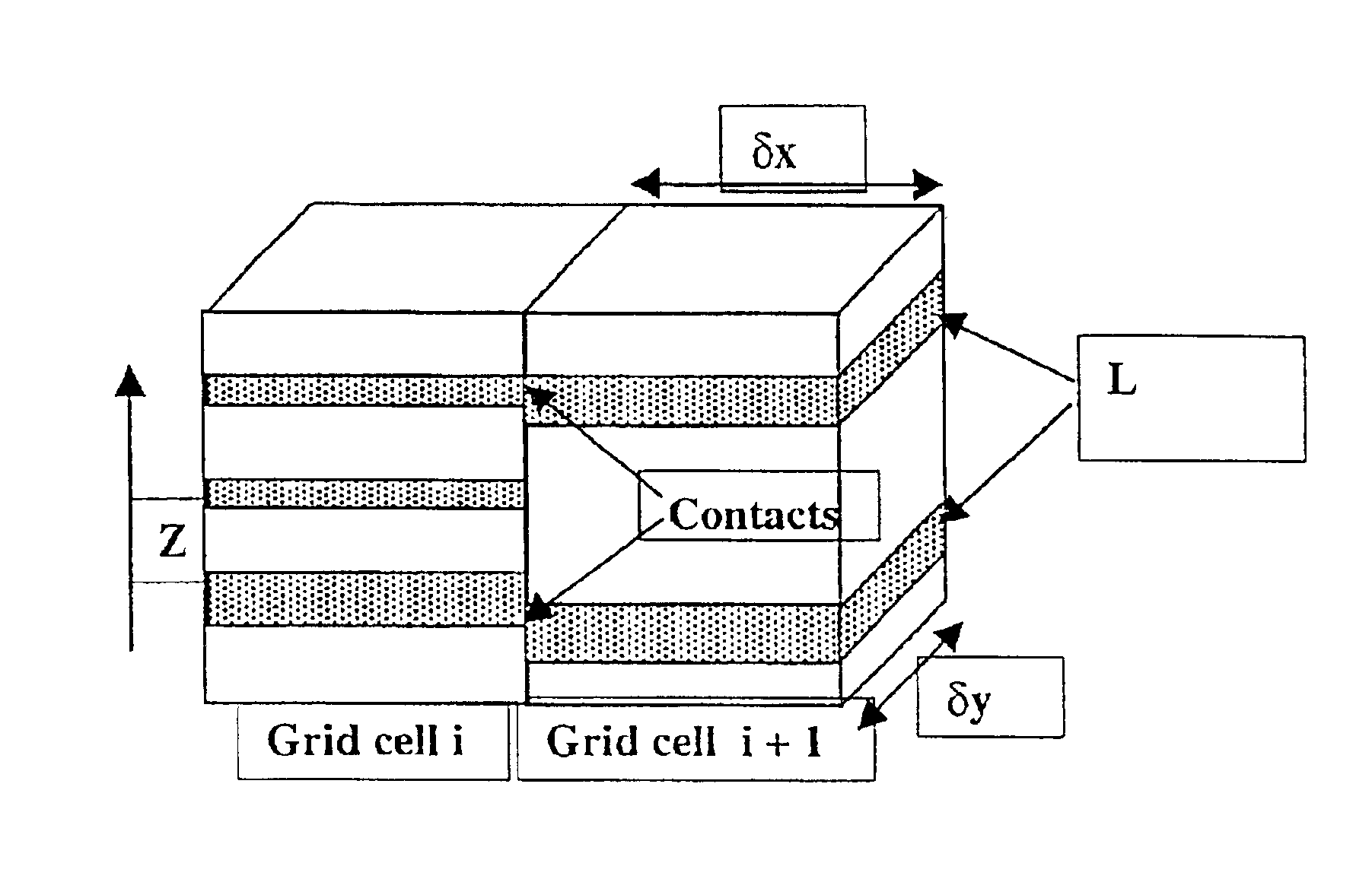
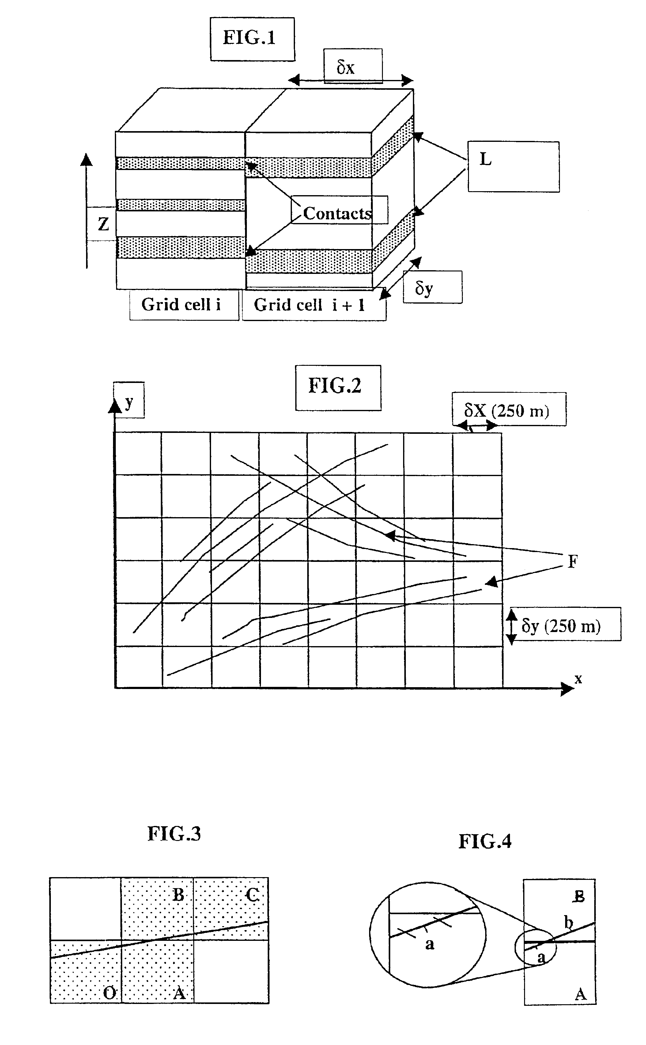
[0029]The example of a porous reservoir crossed by a network of fractures F (FIG. 2) assumed to be vertical for simplification reasons and by thin sedimentary levels (sub-horizontal) L (FIG. 1) whose petrophysical properties (permeability notably) contrast with the matrical surrounding medium is described hereafter. This reservoir is modelled in form of two “superimposed” grids (double medium model), one of which, referred to as “matrix”, representing the surrounding matrix medium, the other, referred to as “fracture”, representing all the discontinuities considered (fractures and permeable thin levels). The flows are calculated within the matrix grid and the fracture grid respectively. Furthermore, exchange terms connect the unknowns of each pair of matrix and fracture cells of the model by means of suitable formulations. The method described hereafter allows calculation of the transmissivities between “fracture” cells and the “matrix-fracture” exchanges. Exchanges between the matr...


PUM


Abstract

A method for modelling flows in a fractured medium crossed by a network of fluid conducting objects of definite geometry but not homogenizable on the scale of each grid cell of the model (large fractures, sub-seismic faults for example, very permeable sedimentary layers, etc.) which has an application in the evaluation of hydrocarbon reservoirs is disclosed. The method allows simulation fluid of flows in a fractured porous geologic medium of known structure that is discretized with a grid and modelled by considering that each elementary volume of the fractured geologic medium is an equivalent fracture medium and matrix medium on the scale of each cell between which fluid exchanges are determined. The method determines exchanges between the matrix medium and the fracture medium, and modeles the transmissivities of the various cells crossed by each conducting object, so that the resulting transmissivity corresponds to the direct transmissivity along each conducting object. Explicit modelling of these objects, which is prohibitive on the scale of a field because of the very large number of cells involved and of the numerical constraints, is therefore unnecessary.

Description

BACKGROUND OF THE INVENTION[0001]1. Field of the Invention[0002]The present invention relates to a method for modelling fluid flows in a fractured medium crossed by relatively large fractures, as specified hereafter.[0003]2. Description of the Prior Art[0004]In a reservoir under production, the pressure and flow rate conditions imposed for the producing and injection wells induce flows of the fluids in place in the reservoir (oil, gas and water). Simulation of these flows determines the evolution of the pressures and of the saturations in the reservoir in the course of time. Because of the very heterogeneous nature of fractured reservoirs, the fluids move relatively fast through the network of fractures and much more slowly in the matrix. Simulation of flows in the context of a fractured reservoir therefore requires a very good representation of the major heterogeneities formed by the fractures. The accuracy of this representation depends on the type of simulation used and on the si...

Claims


Application Information

Patent Timeline
IPC IPC(8): E21B49/00G01V11/00
CPCE21B49/00G01V11/00
Inventor MANCEAU, EMMANUELSARDA, SYLVAINCOSENTINO, LUCACACAS, MARIE-CHRISTINEBOURBIAUX, BERNARD
Owner INST FR DU PETROLE
Why Eureka
Try Eureka