System and method for balancing a driveline system

a driveline and system technology, applied in mechanical equipment, manufacturing tools, instruments, etc., can solve the problems of unbalanced drive shafts, unbalanced drive shafts, and unbalanced drive shafts during use, so as to reduce the error

Inactive Publication Date: 2005-08-02
TORQUE TRACTION TECH INC
View PDF13 Cites 49 Cited by
  • Summary
  • Abstract
  • Description
  • Claims
  • Application Information

AI Technical Summary

Benefits of technology

[0010]The invention would reduce this error in different styles

Problems solved by technology

Because of manufacturing inaccuracies, both the tubes and the universal joints are typically unbalanced for rotation.
Thus, when the tubes and the universal joints are assembled, the drive shaft is generally also unbalanced for rotation.
Similarly, the input shafts of the axles are also typically unbalanced for rotation during use.
It is well known that undesirable noises and vibrations are generated during use if the drive shaft and the axle input shaft are not precisely balanced for rotation.
However, it has been found that when an individually balanced drive shaft and an individually balanced axle input shaft are connected together in the vehicle drive train system, the combined unit may be unbalanced for rotation.
The unbal

Method used


Image

  • System and method for balancing a driveline system
  • System and method for balancing a driveline system
  • System and method for balancing a driveline system

Examples


Embodiment Construction

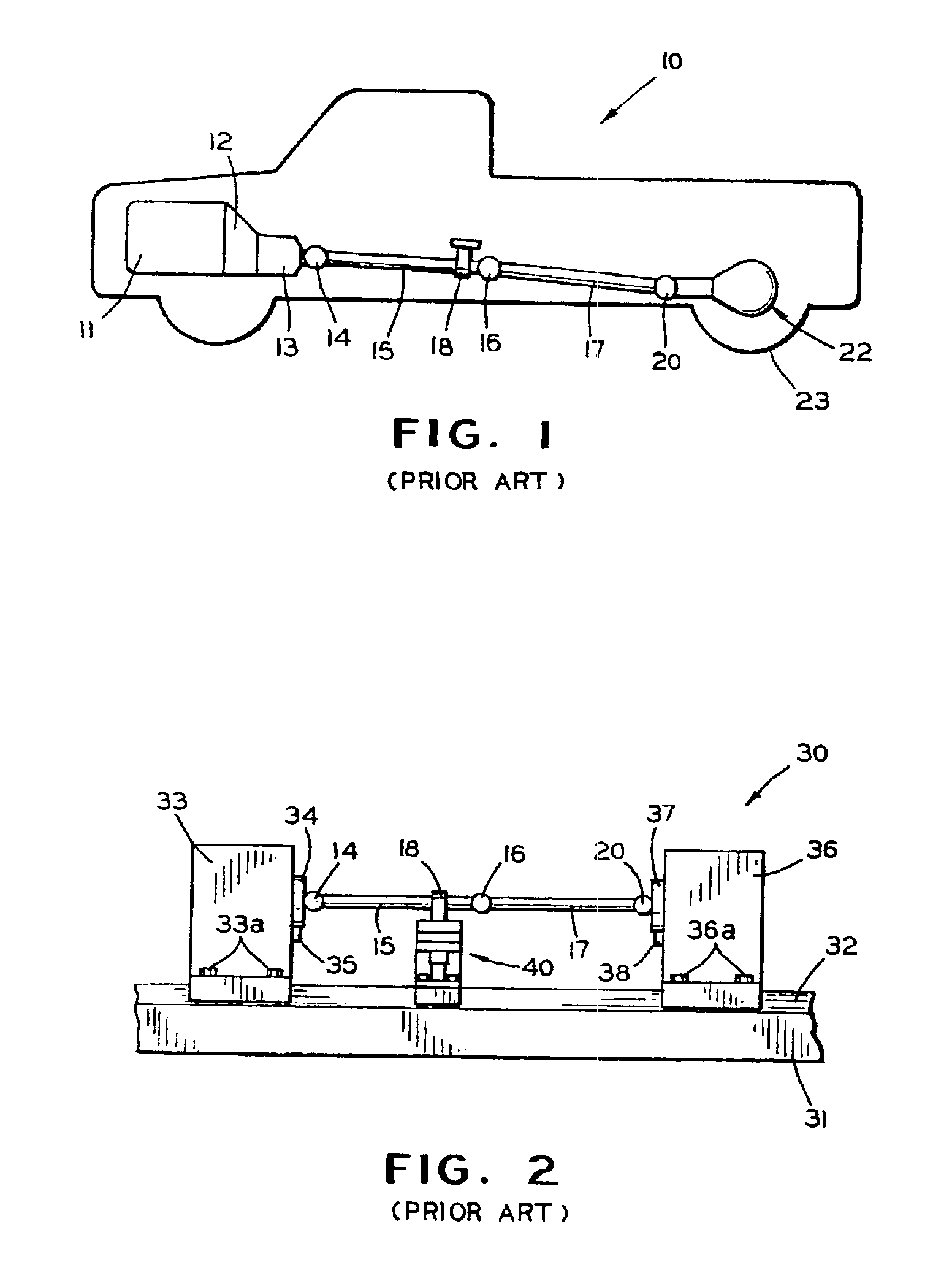
[0021]Referring now to the drawings, there is schematically illustrated in FIG. 1 a vehicle, indicated generally at 10, including a conventional drive train system. The drive train system includes an engine 11, a clutch 12, and a transmission 13. As is well known, the engine 11 includes an output shaft (not shown) which is selectively connected through the clutch 12 to an input shaft (not shown) of the transmission 13. The transmission 13 provides a plurality of speed change gear ratios between the rotational speeds of the input shaft thereto and an output shaft (not shown).

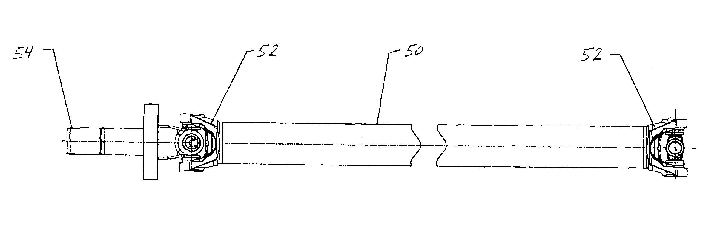
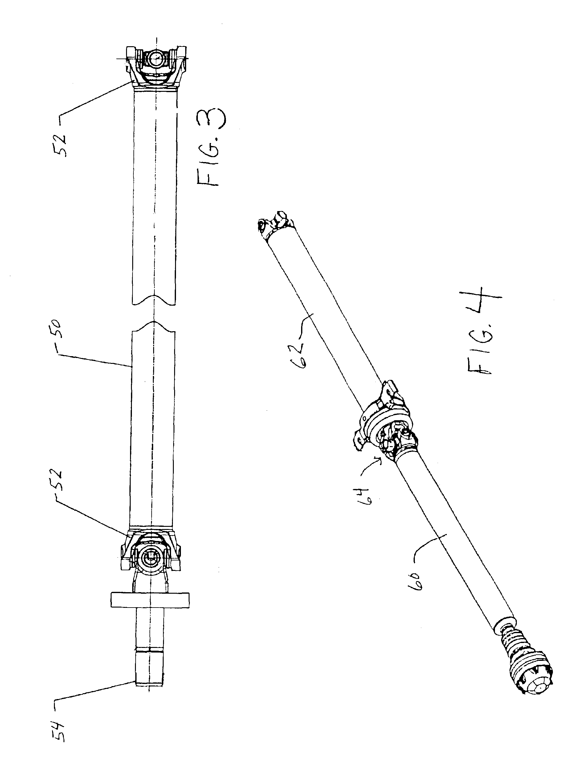
[0022]The output shaft of the transmission 13 is connected by a first universal joint 14 to the forward end of a first drive shaft section 15. The rearward end of the first drive shaft section 15 is connected by a second universal joint 16 to the forward end of a second drive shaft section 17. A conventional center bearing assembly 18 is secured to the frame of the vehicle 10 for rotatably supporting the rearward...


PUM

PropertyMeasurementUnit
Angleaaaaaaaaaa
Angleaaaaaaaaaa
Weightaaaaaaaaaa

Abstract

A process for balancing a vehicular driveline including a propeller shaft and an input shaft of a vehicle axle interconnected by a universal joint. First, the vehicle propeller shaft is balanced to a predetermined residual imbalance having an imbalance vector angle of 0° or 180° which lies inline with open set of cardan joint trunnions. The corrected residual imbalance is then visually marked. Next, the input shaft is balanced to a predetermined residual imbalance having an imbalance vector angle of 0° or 180° which lies inline with cross-holes in yoke ears. Again, the corrected residual imbalance on the input shaft is then visually marked. During the assembly of the vehicle, the assembly line operator couples the propeller shaft to the input shaft through a cardan joint cross by aligning the marks on the propeller shaft and the input shaft so that the marks are located opposite to each other.

Description

FIELD OF THE INVENTION[0001]The invention provides a system and method for improving the vibrational characteristics of a vehicle drive train system or similar rotating shaft components connected through a universal joint.DESCRIPTION OF RELATED ART[0002]Most vehicles provide a drive train system for transmitting power from a source of rotational power, such as an internal combustion or diesel engine, to a plurality of rotatably driven wheels. A typical drive train system includes a clutch, a transmission, a drive shaft, and an axle connected between the engine and the driven wheels. The clutch is connected to the engine for selectively providing a driving connection therethrough to the transmission. The transmission provides a plurality of speed change gear ratios between the clutch and the drive shaft. The drive shaft is elongated so as to transmit the rotational power from the transmission to the vicinity of the driven wheels. The axle includes an elongated input shaft which is co...

Claims


Application Information

Patent Timeline
IPC IPC(8): F16F15/20F16F15/00F16F15/32G01M1/24G01M1/00
CPCF16F15/20F16F15/322G01M1/24Y10T464/50Y10S29/901Y10T29/49778
Inventor NIEMAN, ANDREW L.SHANNON, KERRY
Owner TORQUE TRACTION TECH INC
Why Eureka
Try Eureka