Activating ball assembly for use with a by-pass tool in a drill string

Inactive Publication Date: 2005-08-02
SCHOELLER-BLECKMANN OILFIELD EQUIPMENT
View PDF11 Cites 65 Cited by
  • Summary
  • Abstract
  • Description
  • Claims
  • Application Information

AI Technical Summary

Benefits of technology

[0009]The present invention has therefore been developed primarily with a view to facilitating improved

Problems solved by technology

During typical drilling operations, problems often arise because of differences in the pressures in the geological formation being drilled and at the surface, or between the pressure of the drilling mud and the formation pressure.
Major problems arising out of this include blow-outs, differential sticking and mud circulation loss.
Any of these problems can be very dangerous, and often require expensive solutions.
However, when a problem arises (e.g. a lost circulation condition, when drilling fluid is being lost to the forma

Method used


Image

  • Activating ball assembly for use with a by-pass tool in a drill string
  • Activating ball assembly for use with a by-pass tool in a drill string
  • Activating ball assembly for use with a by-pass tool in a drill string

Examples


first embodiment

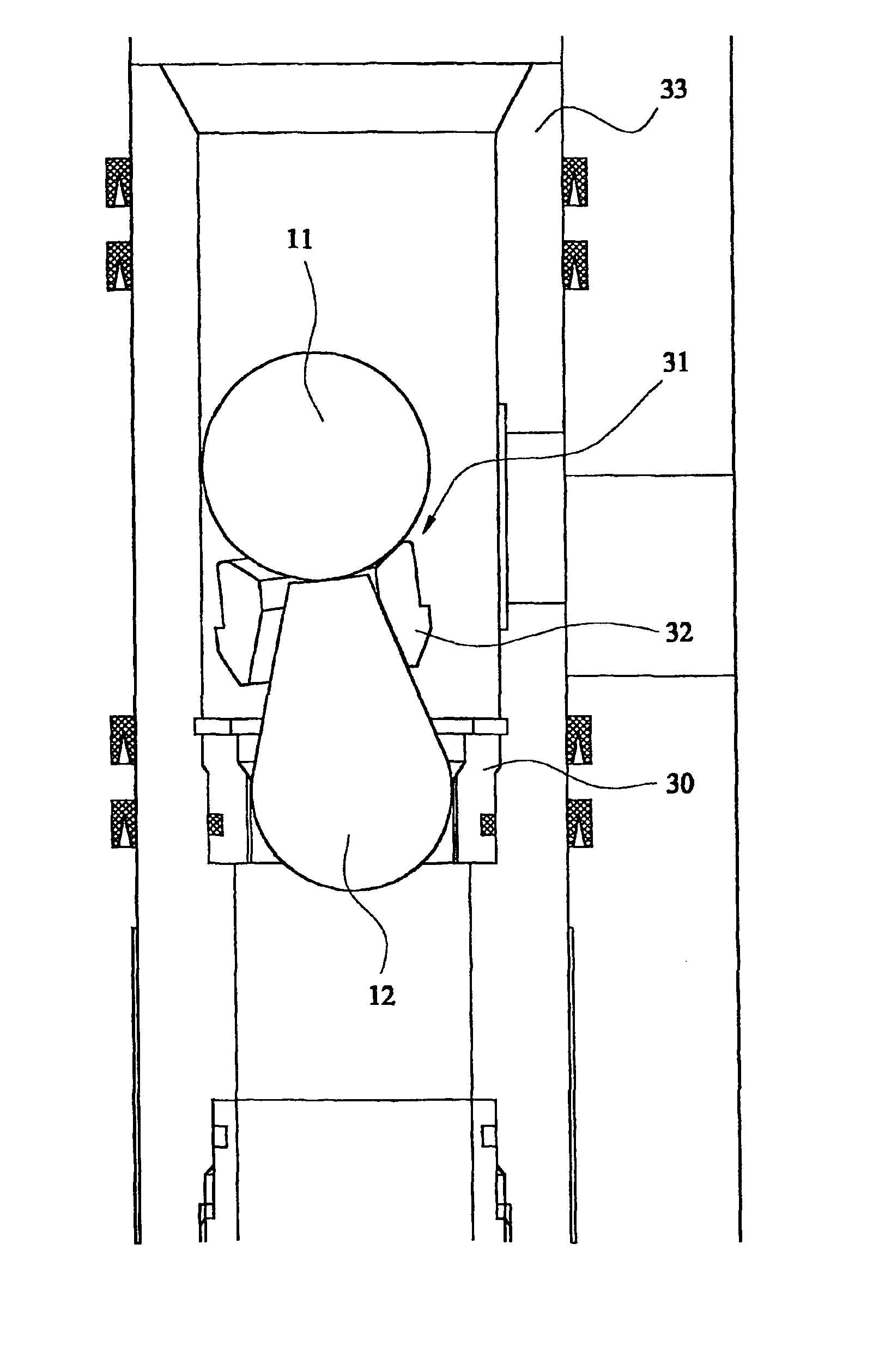
[0041]In FIG. 5, there is shown activating ball assembly according to the invention, designated generally by reference 10. The assembly comprises a large deformable ball 11, which is similar to the ball 20 disclosed in the U.S. patent. The ball 11 is therefore of a size sufficient to engage and to be held captive by the valve seat which it engages in order to activate the by-pass tool, but is deformable so as to subsequently be capable of being forced downwardly through the valve seat after launching of a second and smaller hard de-activating ball.

[0042]A weight 12 is attached to the ball 11, preferably by a threaded connection and augmented by adhesive. The weight 12 is made of non-magnetic material, of which a suitable material is brass.

[0043]The weight 12 is operative to assist in movement of the assembly 10 under the action of gravity to engage the ball 11 with the valve seat, and in that at least a central core of the weight 12 is of smaller transverse dimensions than the ball ...

second embodiment

[0047]However, in some circumstances, it may be desirable to permit a limited proportion of the fluid to continue to flow through the housing, although a major portion of the fluid is still directed to the by-pass port. This may be achieved by the second embodiment which is shown in FIG. 6, in which an open ended narrow passage 13 extends lengthwise of the ball 11 and the weight 12 between an inlet end 14 in the ball 11 and an outlet 15 in the weight 12.

third embodiment

[0048]In a third embodiment, as shown in FIG. 7, means 16 is provided to facilitate unseating of the assembly, if desired, by use of a wireline-delivered retrieval tool. The means 16 comprises a suitable hook-shape, and preferably takes the form of a “fishing neck”17 which is secured to the side of the ball 11 which is opposite to the side of the ball to which the weight 12 is attached.

[0049]In the embodiment shown in FIG. 8, the solid core 12a of the weight has smaller transverse dimensions than the diameter of the valve seat 18, but has resiliently deformable fins 19 projecting outwardly therefrom. These function as wiper blades during the descent down the drill string and the downward forced movement through the valve seat 18, which is permitted by their deformability. Also, this shows the ball dart assembly assembled with the ball seat between the two, locking the ball and dart to the seat. This assembly also allows for fluid to flow from the bottom up, as the dart will not seal...


PUM


Abstract

A by-pass tool to be incorporated in a drill string, in combination with an activating ball assembly operative to adjust the tool between an activated mode and a de-activated mode. The tool has a valve seat engageable by the activating ball assembly to move its sleeve to a by-pass mode which diverts drilling mud from flowing through the housing to a by-pass flow through the by-pass port. The activating ball assembly has a deformable ball of a size sufficient to engage and to be held captive by the salve seat and a weight attached to the ball and operative to assist in movement of the assembly under the action of gravity to engage the ball with the valve seat. The weight has smaller transverse dimensions that the ball so that it moves downwardly through the valve seat and pulls the ball into engagement with the valve seat.

Description

BACKGROUND OF THE INVENTION[0001]This invention relates to a ball assembly for use in activating a by-pass tool in a drill string.[0002]During drilling through the earth's crust in order to reach underground reservoirs of hydrocarbons (gas and / or oil), it is usual to employ a so-called “drill string, and which is driven from the surface, and has a drilling bit on its lower end. It is also usual to employ drilling mud which is conveyed from the surface to the drilling bit via the drill string, in order to lubricate and cool the bit, but which then returns to the surface via the annulus between the drill string and the usual surrounding casing, and also conveying to surface at the same time the “cuttings” formed during the drilling operation.[0003]During typical drilling operations, problems often arise because of differences in the pressures in the geological formation being drilled and at the surface, or between the pressure of the drilling mud and the formation pressure. Major prob...

Claims


Application Information

Patent Timeline
IPC IPC(8): E21B34/00E21B21/00E21B21/10E21B34/14
CPCE21B21/103E21B34/14E21B34/142
Inventor LEE, PAUL BERNARD
Owner SCHOELLER-BLECKMANN OILFIELD EQUIPMENT
Why Eureka
Try Eureka