Drop down trailer

Inactive Publication Date: 2005-08-02
RJKL
View PDF8 Cites 22 Cited by
  • Summary
  • Abstract
  • Description
  • Claims
  • Application Information

AI Technical Summary

Benefits of technology

[0014]Accordingly it is the object of the present invention to provide a trailer which can be easily lowered to ground level or raised from ground level by simply raising or lowering an arm and handle assembly located on each side of the trailer. The use of a arm and handle system for raising and lowering the trailer, avoids the danger and undependable nature of winch and pulley systems. Similarly, the present invention allows items to be loaded at ground level, thereby avoiding the dangers posed by trailers requiring a tilting platform. It is the further object of this invention to serve as an ice fishing house, whereby the trailer can be pulled onto a frozen lake or river, lowered onto the ice, and then used as an enclosed ice fishing house.
[0015]It is a further object of this invention to provide such a trailer with a suspension system permitting the raising and lowering of the trailer platform within the main frame, by having no common axle but rather rubber torsion stub axles for each wheel, such suspen

Problems solved by technology

However, the angle at which the trailer must be titlted is quite large which makes the loading or heavy items very difficult and hazardous.
The prior art trailer required a great amount of power to raise the bed and the equipment thereon to the raised position.
In addition, the failure of a rope, pulley or winch on the prior art trailer would result in damage to the trailer, the objects placed upon the trailer and possible injury to individuals.
The load-bearing platform can be lowered as far as such center portion, but can only be as wide as the center portion, which limits the load to a single motorcycle.
This design forces the load-carrying bed to move forward and backward as well as up and down, requiring the entire framework not including the tongue to be longer than the lo

Method used


Image

  • Drop down trailer
  • Drop down trailer
  • Drop down trailer

Examples


Example

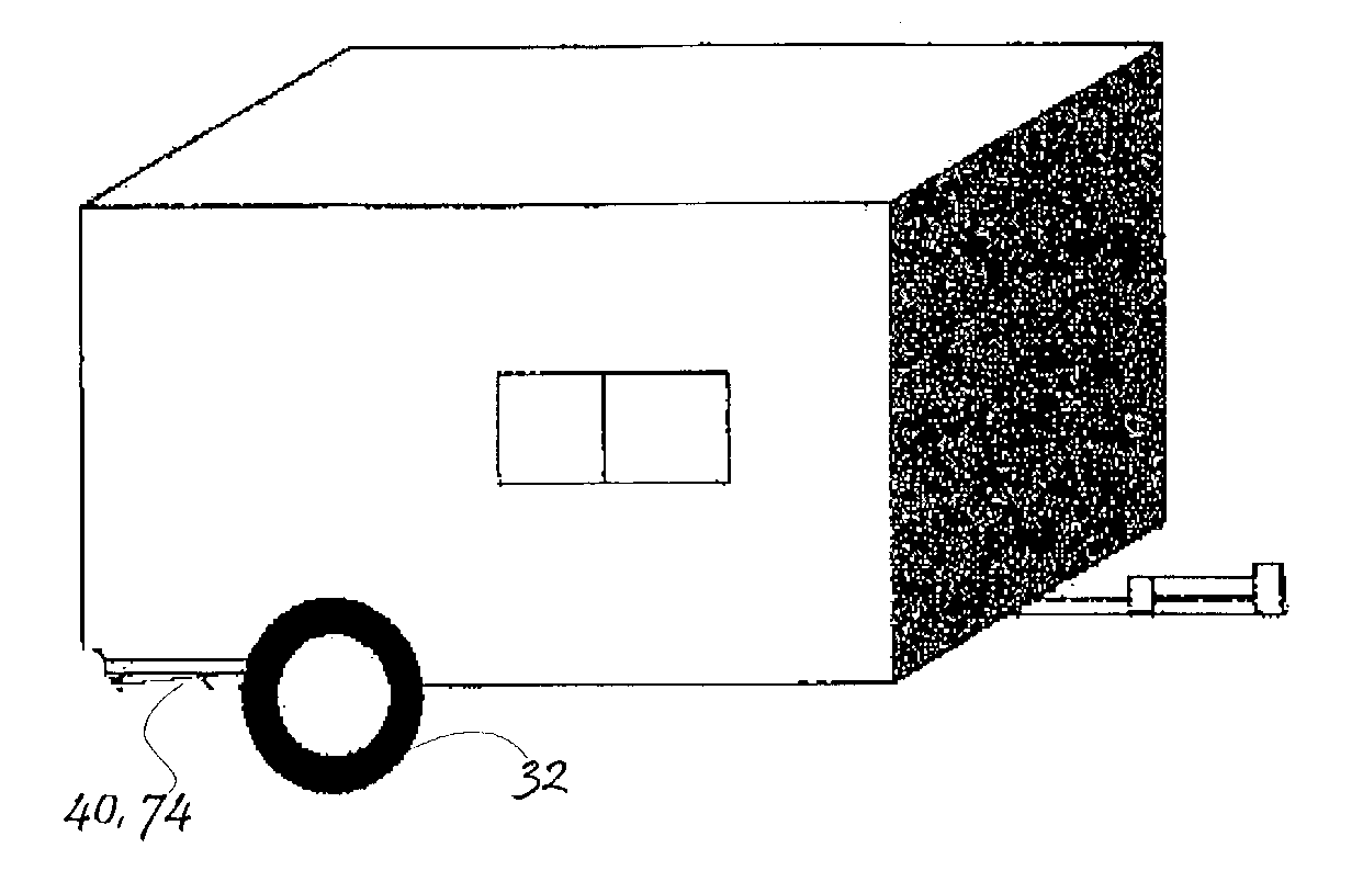
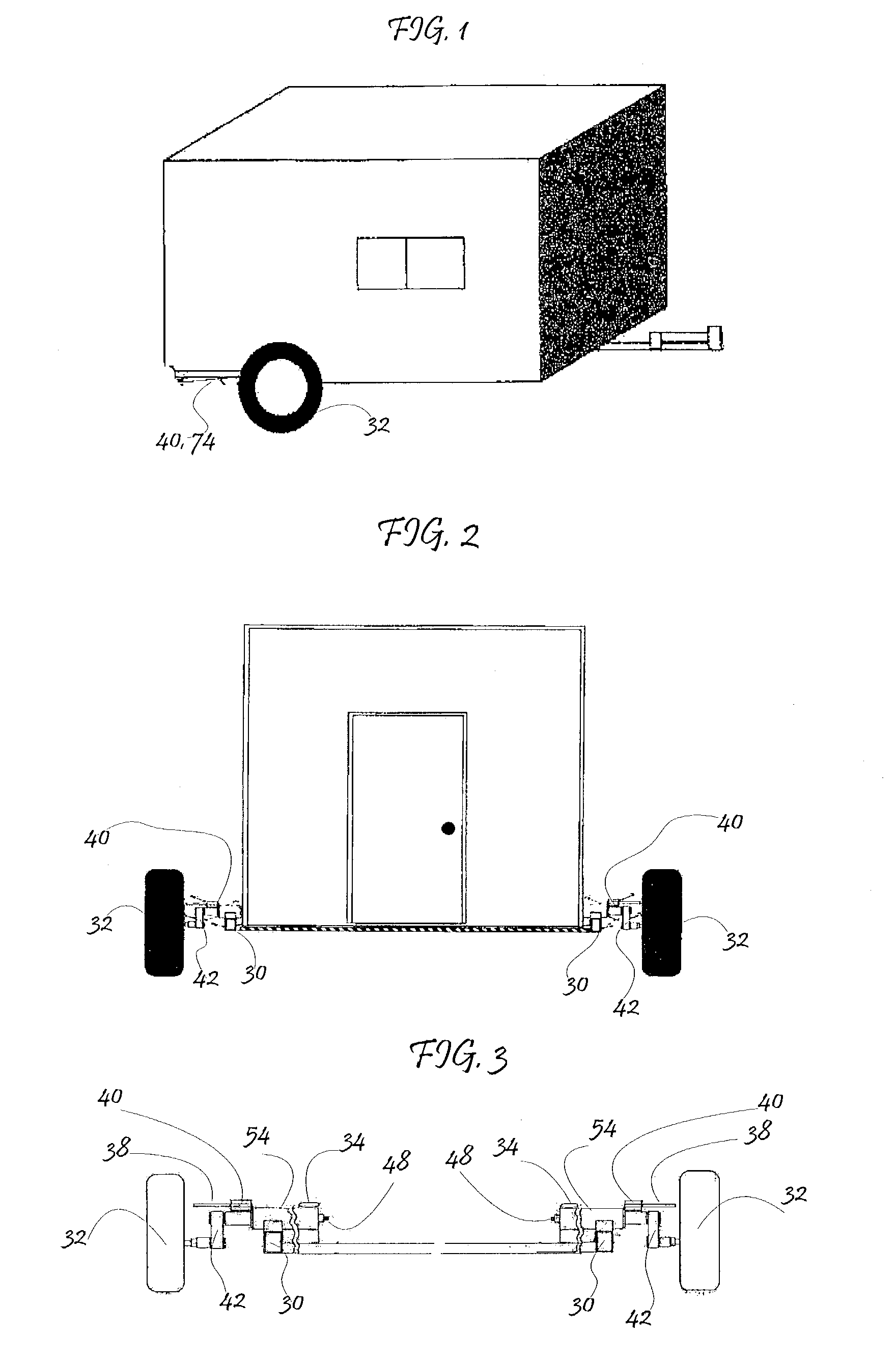
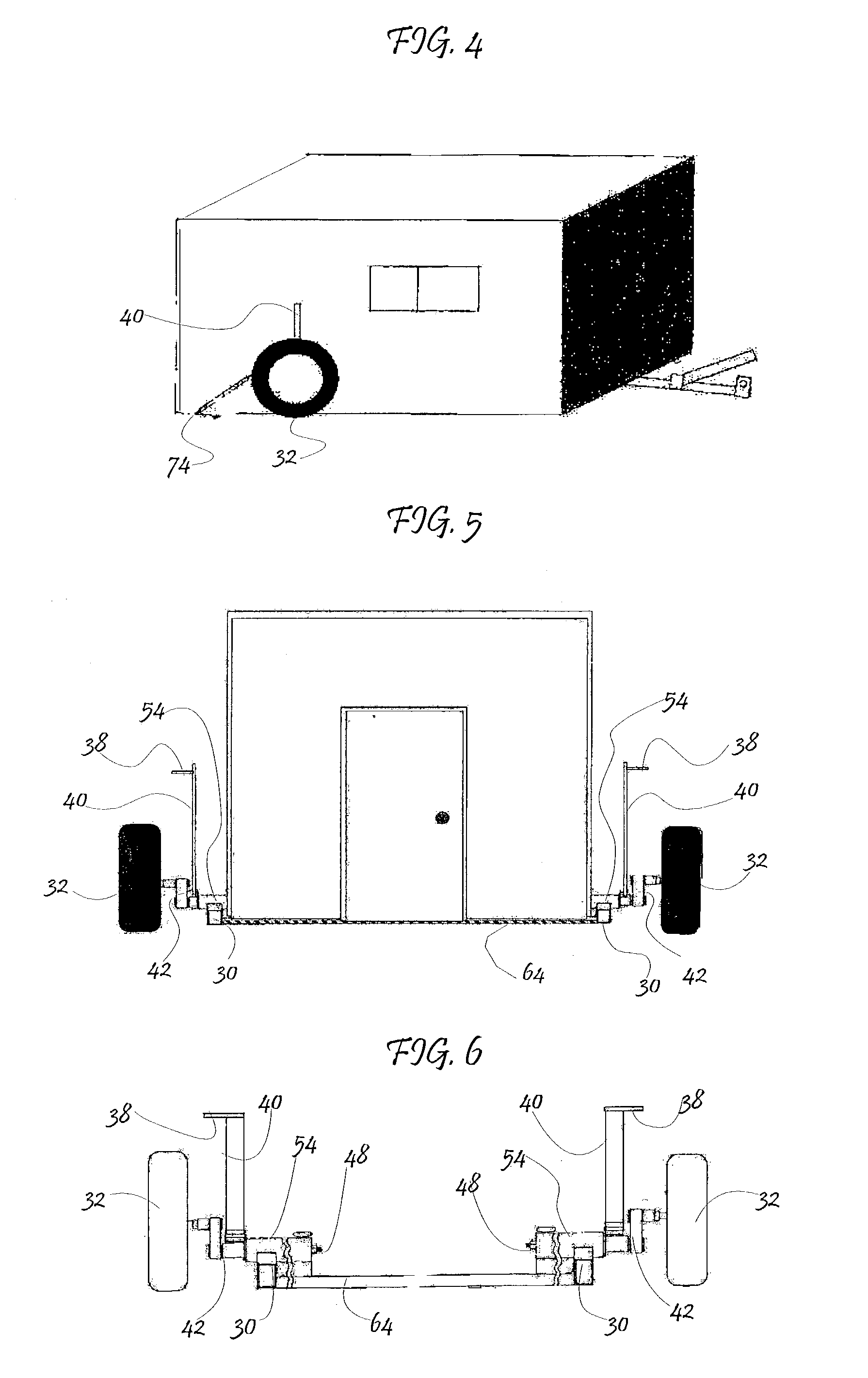
[0039]Referring to FIGS. 1 through 17, a ground-level trailer for use as an ice fishing house or for loading and unloading hauled items consists of a rectangular shaped frame members 30 with cross members 64; a tongue assembly attached to the front end frame member (not shown); at least one pair of wheels 32 rotating on rubber torsion stub axles 42 connected to the frame members and cross members (FIG. 10) through a pair of cylindrical piping assemblies; arm and handle assemblies (FIG. 6) attached to each of the rubber torsion stub axle assemblies (FIGS. 7, 11) which can be rotated to raise or lower the frame members 30 and cross members 64 (FIGS. 1,2,3,4,5,6); fender support brackets (FIG. 13) attached to each arm and handle assembly (FIG. 14); and a pair of gas operated springs attached to the frame members 30 of the trailer and the fender support brackets (FIG. 15).

[0040]The trailer includes a frame having frame members 30 and cross members 64. One end of each of the frame member...


PUM


Abstract

A trailer for use as an ice fishing house or for transporting a load from one area to another has a frame and a load bearing platform attached to the frame which is capable of being moved from a travel position to a ground level position. A lifting mechanism is located on each side of the trailer and made a part of the rubber torsion stub axle assembly connected to the trailer frame with the lifting mechanisms being operated by arm and handle assemblies attached to rubber torsion stub axles. When the arm and handle assemblies are rotated to a vertical position, the trailer frame is lowered to the ground level and when the arm and handle assemblies are rotated to a horizontal position, the trailer frame is raised to the travel position. Two securing means are used on each lifting mechanism to secure the frame in the travel position.

Description

CROSS-REFERENCE TO RELATED APPLICATION[0001]This application claims the benefit of Provisional Patent Application Ser. No. 60 / 333,887, filed Nov. 30, 2001.BACKGROUND OF THE INVENTION[0002]1. Field of Invention[0003]This invention relates to automobile trailers, specifically to an improved mechanism to lower the frame of the trailer to ground level.[0004]2. Discussion of Prior Art[0005]The traditional towed trailer has a rigid axle on which the wheels are rotatably supported. The axle is disposed beneath the load floor of the trailer. The body of the trailer is supported above the axle by leaf springs. Two or more shock absorbers are employed between the axle and the trailer floor to dampen the road vibrations. Depending on the load to be transported on the trailer, the wheel will have a rolling radius between twelve and twenty-two inches. This will position the trailer floor approximately eighteen to thrity inches above the ground.[0006]The trailers generally do not have a tiltable ...

Claims


Application Information

Patent Timeline
IPC IPC(8): B60P1/00B60P1/02
CPCB60P1/027
Inventor ZACHMEIER, LEOWALD, TONY
Owner RJKL
Why Eureka
Try Eureka