Device and method for controlling tilt servo

a technology of tilt servo and control device, which is applied in the direction of digital signal error detection/correction, instruments, recording signal processing, etc., can solve the problems of deteriorating the reading accuracy of recorded information, and it is not possible to properly perform the tilt servo control device for unwritten optical disk, so as to reduce the tilt error signal

Inactive Publication Date: 2005-08-02
PIONEER CORP
View PDF10 Cites 25 Cited by
  • Summary
  • Abstract
  • Description
  • Claims
  • Application Information

AI Technical Summary

Benefits of technology

[0008]It is therefore an object of the present invention to provide a tilt servo control device and a tilt servo control method that can properly perform tilt servo control for an optical recording medium into which any information is not written yet.
[0009]The present invention provides a tilt servo control device of an information recording / reproducing apparatus for recording information on and reproducing information from an optical recording medium, the apparatus comprising an optical system for leading a laser beam emitted from a light source to a recording surface of the optical recording medium and a laser beam reflected by the recording surface of the recording medium to a split type photo detector and a read signal generator for generating a read signal in accordance with an output signal of the photo detector. The device comprises a push-pull component generator for generating a push-pull component signal including a differential component of output signals of respective split portions of the photo detector, a tilt error signal generator for generating a tilt error signal representing a tilt angle between a normal to the recording surface of the optical recording medium at a position of the laser beam irradiating the recording surface and an optical axis of the laser beam based on the push-pull component signal, a tilt angle adjuster for adjusting the tilt angle, and a driver for driving the tilt angle adjuster so as to reduce the tilt error signal.
[0010]The present invention provides a tilt servo control method of an information recording / reproducing apparatus for recording information on and reproducing information from an optical recording medium, the apparatus comprising an optical system for leading a laser beam emitted from a light source to a recording surface of the optical recording medium and a laser beam reflected by the recording surface of the recording medium to a split type photo detector and a read signal generator for generating a read signal in accordance with an output signal of the photo detector. The method comprises the steps of generating a push-pull component signal including a differential component of output signals of respective split portions of the photo detector, generating a tilt error signal representing a tilt angle between a normal to the recording surface of the optical recording medium at a position of the laser beam irradiating the recording surface and an optical axis of the laser beam based on the push-pull component signal, and driving a tilt angle adjuster for adjusting the tilt angle so as to reduce the tilt error signal.

Problems solved by technology

If the optical disk has a warp, or errors in the mechanical system are large, it is impossible to irradiate the reading light beam perpendicular to the recording surface of the optical disk, thereby deteriorating reading accuracy for the recorded information.
Therefore, there is a problem in that it is not possible to properly perform the tilt servo control device for the unwritten optical disk.

Method used


Image

  • Device and method for controlling tilt servo
  • Device and method for controlling tilt servo
  • Device and method for controlling tilt servo

Examples


Embodiment Construction

[0033]Embodiments of the present invention will now be described in detail hereinafter with reference to the accompanying drawings.

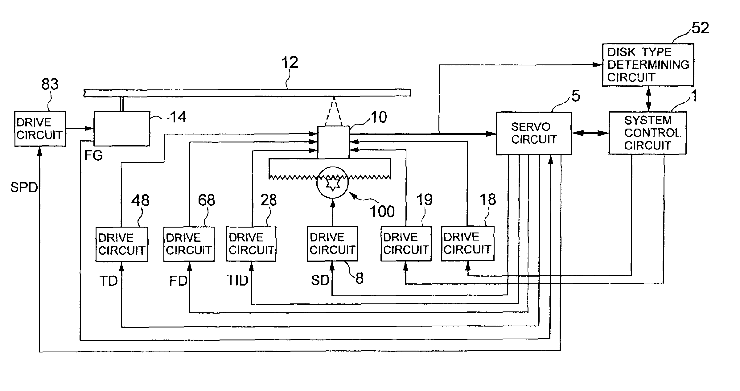
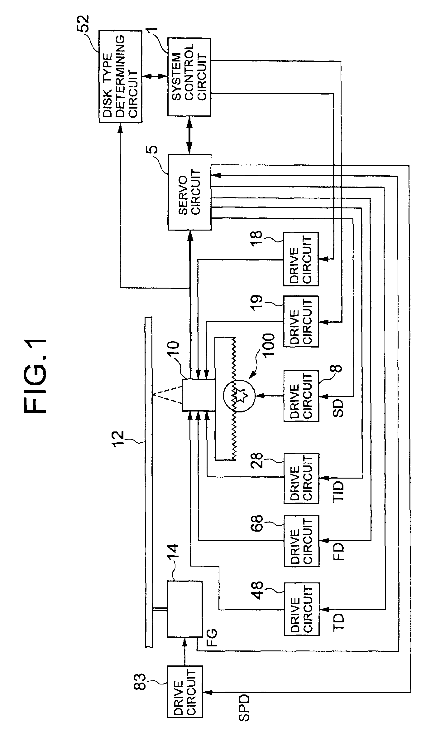
[0034]FIG. 1 is a schematic block diagram of an optical disk player provided with a tilt servo control device according to the present invention. In the illustrated optical disk player, a pickup 10 irradiates a laser beam onto an optical disk 12 and receives a laser beam reflected by the optical disk 12. Then, the pickup 10 generates a signal corresponding to the intensity of the received laser beam. The optical disk 12 is driven to rotate by a motor 14. The optical disk 12 may be a DVD type disk such as a DVD-ROM, a DVD-R, a DVD-RAM and a DVD-RW or a CD type disk such as a CD-ROM and a CD-R. The DVD-RAM has two types, a one-recording-layer disk and a two-recording-layer disk.

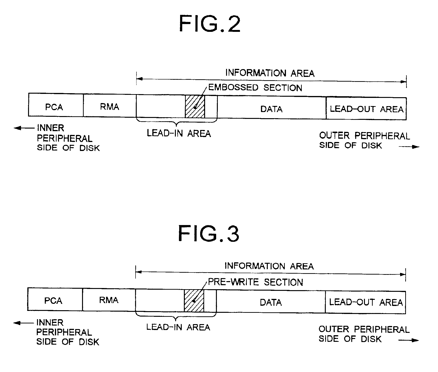
[0035]Referring to FIG. 2, a DVD-RW has data structure including a PCA (power calibration area), an RMA (recording management area), a lead-in area, a data area and a lead-out area ...


PUM

PropertyMeasurementUnit
wavelengthaaaaaaaaaa
tilt angleaaaaaaaaaa

Abstract

A tilt servo control device of an apparatus for recording information on and reproducing information from an optical recording medium, the apparatus comprising an optical system for leading a laser beam emitted from a light source to a recording surface of the optical recording medium and a laser beam reflected by the recording surface of the recording medium to a split type photo detector and a read signal generator for generating a read signal in accordance with an output signal of the photo detector. The tilt servo control device generates a push-pull component signal including a differential component of output signals of respective split portions of the photo detector, generates a tilt error signal representing a tilt angle at a position of the laser beam irradiating the recording surface and an optical axis of the laser beam based on the push-pull component signal, and drives a tilt angle adjuster for adjusting the tilt angle so as to reduce the tilt error signal.

Description

BACKGROUND OF THE INVENTION[0001]1. Field of the Invention[0002]The present invention relates to a tilt servo control device and a tilt servo control method for compensating the tilt angle of a recording surface of an optical recording medium as defined by the angle between the normal to the recording surface of the recording medium and the optical axis of a light beam irradiating the recording surface.[0003]2. Description of the Related Background Art[0004]In order to correctly read information recorded on an optical disk such as a DVD (Digital Versatile Disk), it is necessary to irradiate a reading light beam perpendicularly relative to a recording surface of the optical disk. If the optical disk has a warp, or errors in the mechanical system are large, it is impossible to irradiate the reading light beam perpendicular to the recording surface of the optical disk, thereby deteriorating reading accuracy for the recorded information.[0005]In view of this problem, information reprodu...

Claims


Application Information

Patent Timeline
Patent Type & Authority Patents(United States)
IPC IPC(8): G11B7/125G11B7/135G11B7/095G11B7/0045G11B7/00G11B7/13G11B7/004G11B7/126G11B7/1267G11B7/131G11B7/1369
CPCG11B7/0956G11B7/126G11B7/1267G11B7/131G11B7/1369G11B7/0045G11B2007/0006
Inventor YANAGAWA, NAOHARUKATO, MASAHIRO
Owner PIONEER CORP
Why Eureka
Try Eureka