
Diverter spout

a technology of diverter spout and spout, which is applied in the direction of mechanical equipment, transportation and packaging, functional valve types, etc., can solve the problems of collision force in water, unreliable water pressure, and leakage of conventional diverter spout, so as to avoid leakage and reliably divert water flow

Inactive Publication Date: 2005-08-09
GLOBE UNION INDAL
View PDF4 Cites 23 Cited by
  • Summary
  • Abstract
  • Description
  • Claims
  • Application Information

AI Technical Summary

Benefits of technology

[0009]Accordingly, an object of the present invention is to provide a diverter spout, which reliably diverts water flow so that water controllably flows through only a drain opening or only a spout and effectively avoids leakage.
[0010]Another object of the present invention is to provide a diverter spout, which is manufactured easily.

Problems solved by technology

However, there are some deficiencies as below.
Firstly, the conventional diverter spout tends to leak.
However, the water pressure is unreliable.
Moreover, there is collision force in water.
Thus the through hole 53 is covered incompletely, resulting in leakage of the drain opening 50.
Secondly, the conventional diverter spout requires rather precise manufacture.
The partition wall 52 is formed at interior of the drainpipe 5, increasing difficulties in manufacture.

Method used


Image

  • Diverter spout
  • Diverter spout
  • Diverter spout

Examples


Embodiment Construction

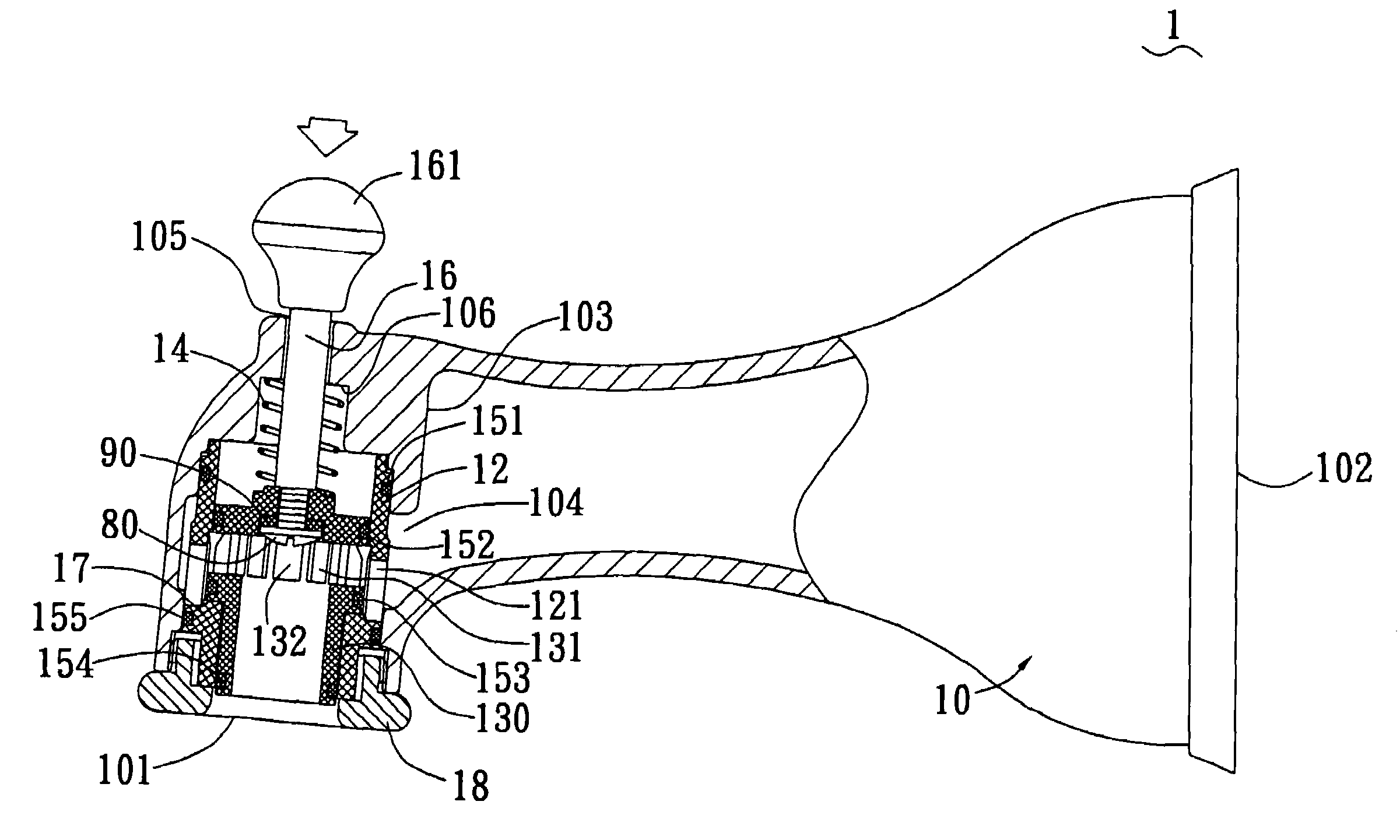
[0020]With reference to FIG. 4, a diverter spout 1 of the present invention comprises a drain pipe 10, a connecting sleeve 12, an offset shaft 13, a resilient element 14, leakproof rings 151, 152, 153, 154, 155, a pole 16, a supporting sleeve 17 and an envelope 18. The drainpipe 10 defines a drain opening 101 for draining water and an assembling opening 102 for assembling to a water pipe. Further referring to FIG. 5, the drainpipe 10 forms an inner wall 103 between the drain opening 101 and the assembling opening 102. A through hole 104 is defined through a lower portion of the inner wall 103 for water flowing therethrough. A mounting hole 105 is defined in the drainpipe 10 and adjacent to the drain opening 101 for mounting the pole 16. A flute 106 is defined below the mounting hole 105 for abutting an end of the resilient element 14. In one embodiment, the resilient element 14 is a spring. The resilient element 14 has such spring coefficient that is larger than interferential frict...


PUM


Abstract

A diverter spout has a drain pipe, a connecting sleeve, an offset shaft, a resilient element between the drain pipe and the offset shaft, a pole for manual operation, a supporting sleeve and an envelope. At least a leakproof rubber ring is mounted around the offset shaft. Due to interferential friction between the leakproof rings and the connecting sleeve or the supporting sleeve and water pressure, a blocking portion of the offset shaft controls the water to flow only through a spout. In normal state, the resilient element overcomes interferential friction between the leakproof rings and the connecting sleeve or the supporting sleeve and controls the water to flow only through a drain opening of the drainpipe. Therefore, water diverts reliably without leakage.

Description

BACKGROUND OF THE INVENTION[0001]1. Field of the Invention[0002]The present invention relates to a diverter spout, and particularly to a diverter spout which is assembled with a spout and which reliably controls water so that water flows through only the diverter spout or only the spout and that water flows only through the diverter spout when water resource is shut off.[0003]2. Related Art[0004]As shown in FIG. 1, a conventional diverter spout, which is adapted to assemble with a spout, comprises a drain pipe 5, a control element 6, a pole 7 and a leakproof gasket 8. Further referring to FIG. 2, the drainpipe 5 defines a drain opening 50 and an assembling opening 51. A partition wall 52 is formed on the drainpipe 5 and defines a through hole 53 therein. A mounting hole 54 is defined in the drainpipe 5 for mounting the pole 7. The control element 6 includes an offset block 61 and a seal gasket 62. The offset block 61 defines a recess 610 in the vicinity of the through hole 53 for re...

Claims


Application Information

Patent Timeline
IPC IPC(8): E03C1/04
CPCE03C1/0404E03C2201/30Y10T137/9464
Inventor TAN, WANG-HONGXIA, PENG-CHENG
Owner GLOBE UNION INDAL
Features
  • Generate Ideas
  • Intellectual Property
  • Life Sciences
  • Materials
  • Tech Scout
  • Unparalleled Data Quality
  • Higher Quality Content
  • 60% Fewer Hallucinations
Learn More