Method for extracting carbon dioxide for use as a refrigerant in a vapor compression system

a technology of vapor compression system and carbon dioxide, which is applied in the direction of domestic cooling apparatus, lighting and heating apparatus, transportation and packaging, etc., can solve the problems of increasing the possibility of refrigerant leakage, affecting the environment, and phasing out chlorine based refrigerants

Inactive Publication Date: 2005-08-09
CARRIER CORP
View PDF10 Cites 61 Cited by
  • Summary
  • Abstract
  • Description
  • Claims
  • Application Information

AI Technical Summary

Problems solved by technology

Chlorine based refrigerants have been phased out in most of the world due to a possible detrimental effect on the environment.
Hydrofluoro carbons (HFCs) have been used as replacement refrigerants, but these refrigerants may still be detrimental to the environment.
The possibility of refrigerant leakage increases when a vapor compression system runs with carbon dioxide due to the high operating pressure.
However, adding additional charge to a vapor compression system is both costly and labor intensive.

Method used


Image

  • Method for extracting carbon dioxide for use as a refrigerant in a vapor compression system
  • Method for extracting carbon dioxide for use as a refrigerant in a vapor compression system
  • Method for extracting carbon dioxide for use as a refrigerant in a vapor compression system

Examples


first embodiment

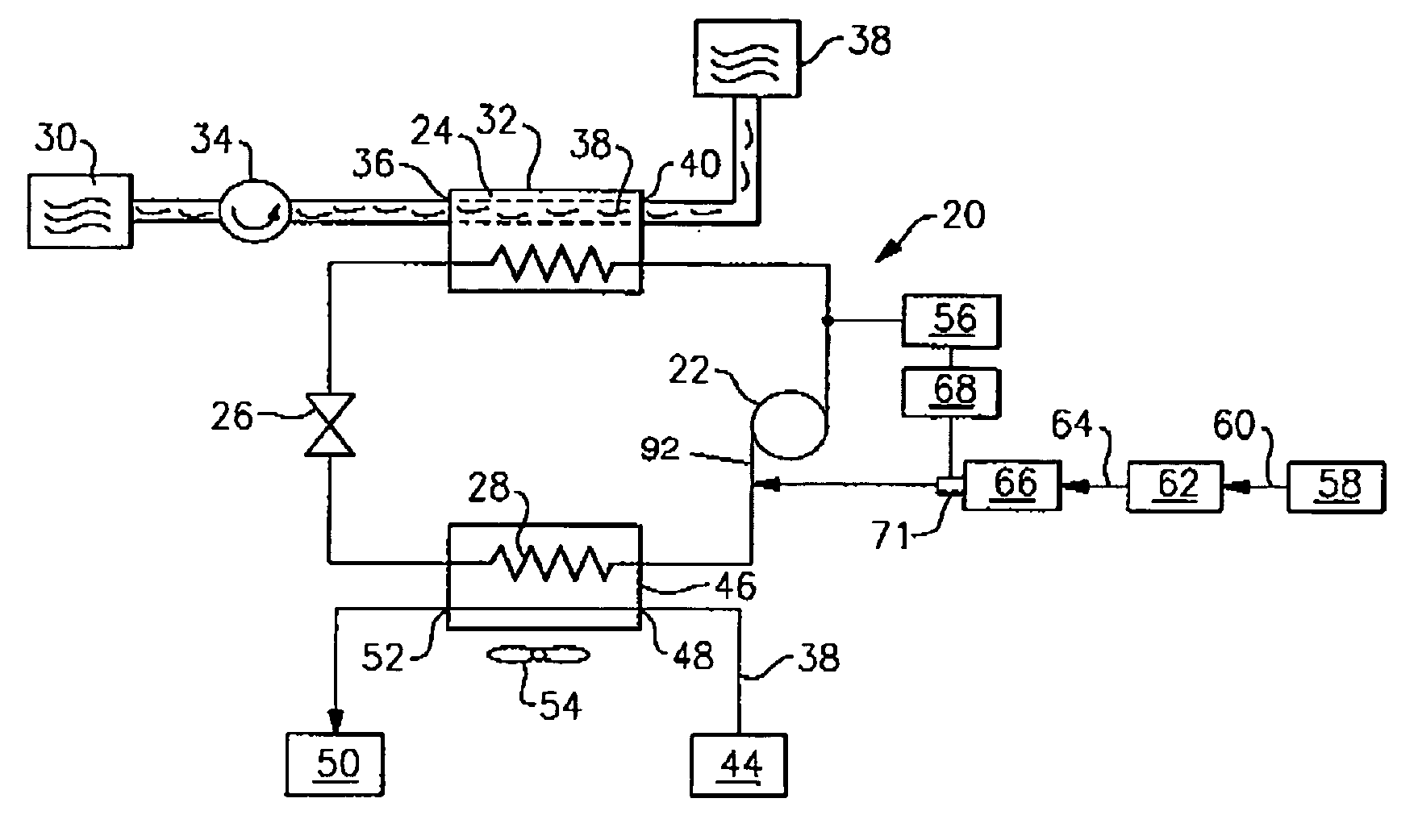
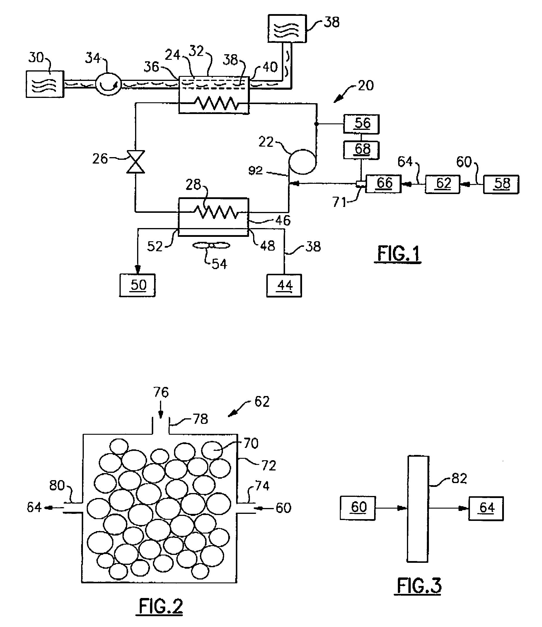
[0024]In a first embodiment, as shown in FIG. 1, an internal combustion engine 58 produces an exhaust gas stream of combustion products 60 including carbon dioxide 64. The carbon dioxide 64 is extracted from the combustion products 60 by a carbon dioxide extraction system 62. The extracted carbon dioxide 64 is then directed to and stored in a storage tank 66. A pump or compressor 90 can be used to increase the pressure of the carbon dioxide in the storage tank 66 to allow the carbon dioxide to be more easily used by the system 20. By extracting carbon dioxide 64 from the combustion products 60, the amount of carbon dioxide emitted into the atmosphere is reduced, reducing pollution.

[0025]A sensor system 56 detects the amount of refrigerant in the system 20. When the sensor 56 detects or estimates that the amount of the refrigerant in the system 20 is below a threshold value, charge has leaked from the system. The sensor system 56 sends a signal to a control 68, indicating that the re...

second embodiment

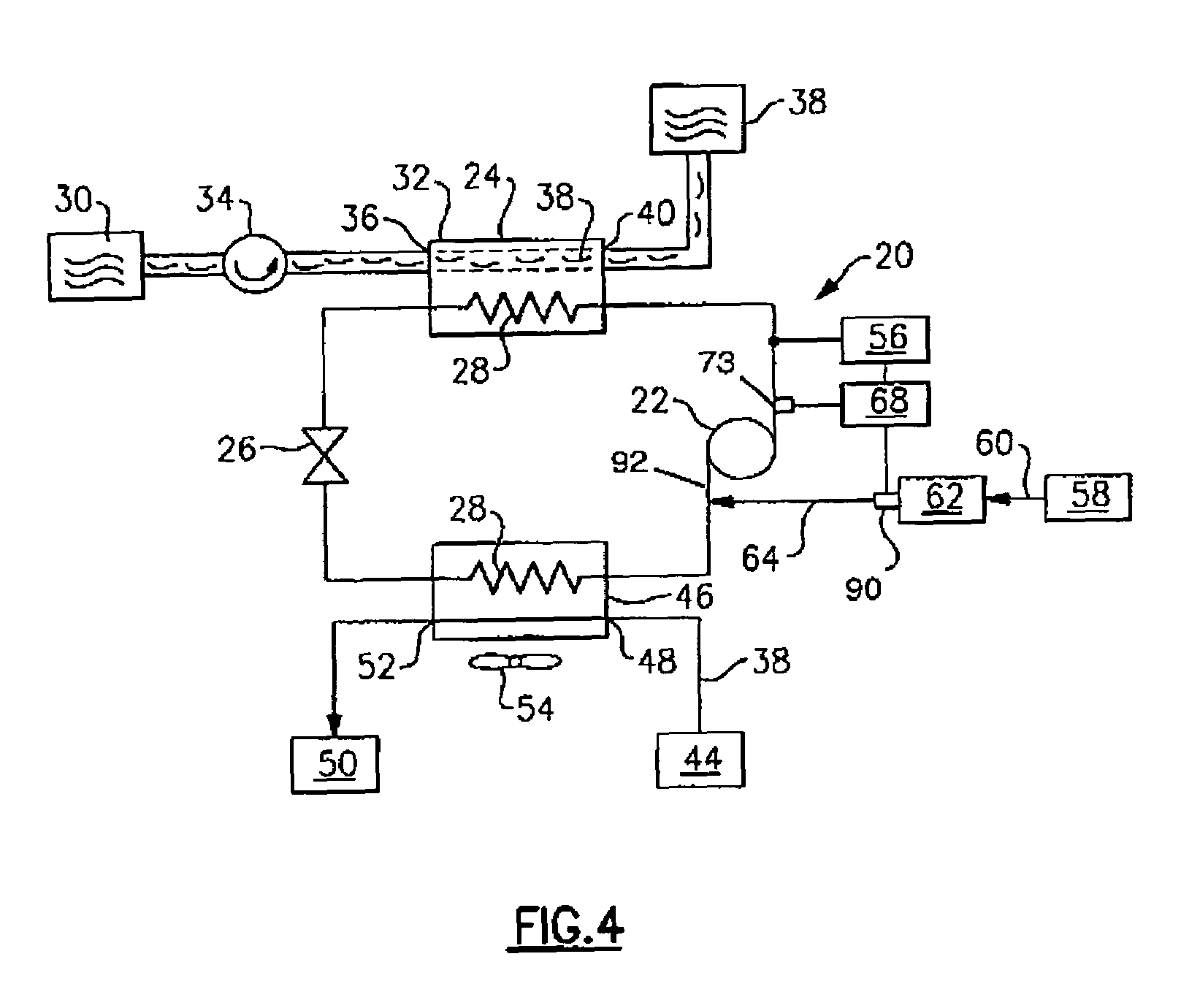
[0033]FIG. 4 schematically illustrates the present invention. After the carbon dioxide 64 is extracted from the combustion products 60 by the carbon dioxide extraction system 62, the carbon dioxide 64 is directly added to the system 20. A small pump or compressor 90 may be used to raise the pressure of the carbon dioxide from the extraction system 61 to the system 20 pressure. The carbon dioxide 64 can be added at any point in the system 20. Preferably, the carbon dioxide 64 is added add at the suction 92 of the compressor 22 as this is where the pressure of the system 20 is the lowest.

[0034]The sensor system 56 detects or estimates the amount of carbon dioxide refrigerant in the vapor compression system 20. When the sensor system 56 detects or estimates that the amount of the refrigerant in the system 20 is above a threshold value, there is too much charge in the system 20. The sensor system 56 sends a signal to a control 68, indicating that the refrigerant level is above the thres...


PUM


Abstract

Carbon dioxide refrigerant is circulated through a vapor compression system including a compressor, a gas cooler, an expansion device, and an evaporator. Carbon dioxide is extracted from a vehicle exhaust stream that includes combustion products of burned hydrocarbon fuel. The extracted carbon dioxide is used to supplement the initial supply of carbon dioxide refrigerant to maintain a desired (or predetermined) level of refrigerant in the system. The system includes a sensor assembly that measures and monitors the amount of refrigerant in the system. In one example, the extracted carbon dioxide is automatically added to the system from a storage tank when a sensor detects that the amount of carbon dioxide refrigerant in the system is below a threshold value. In another example, the extracted carbon dioxide is directly added to the system, and the carbon dioxide refrigerant is purged from the system when a sensor detects that the amount of carbon dioxide in the system exceeds a threshold value.

Description

BACKGROUND OF THE INVENTION[0001]The present invention relates generally to a method for extracting carbon dioxide from of an internal combustion engine exhaust and automatically adding the extracted carbon dioxide to a vapor compression system for use as a refrigerant.[0002]Chlorine based refrigerants have been phased out in most of the world due to a possible detrimental effect on the environment. Hydrofluoro carbons (HFCs) have been used as replacement refrigerants, but these refrigerants may still be detrimental to the environment.[0003]“Natural” refrigerants, such as carbon dioxide and propane, have been proposed as replacement fluids. Carbon dioxide can be used as a refrigerant in automotive air conditioning systems and other heating and cooling applications. Carbon dioxide has a low critical point, which causes most air conditioning systems to run transcritically, or partially above the critical point, under most conditions.[0004]The possibility of refrigerant leakage increas...

Claims


Application Information

Patent Timeline
Patent Type & Authority Patents(United States)
IPC IPC(8): F25B9/00F25B45/00B60H1/32
CPCB60H1/3225F25B9/008F25B45/00F25B2309/06F25B2345/001F25B2700/04
Inventor SIENEL, TOBIAS H.
Owner CARRIER CORP
Why Eureka
Try Eureka