Supercritical pressure regulation of economized refrigeration system by use of an interstage accumulator

a technology of accumulator and economized refrigeration system, which is applied in the direction of refrigeration components, refrigeration machines, lighting and heating apparatus, etc., can solve the problems of low criticality of carbon dioxide and use of many fluids in the system, and achieve the effects of increasing the superheat of the refrigerant, increasing the amount of refrigerant in the system, and reducing the system's high pressur

Inactive Publication Date: 2008-09-16
CARRIER CORP
View PDF24 Cites 31 Cited by
  • Summary
  • Abstract
  • Description
  • Claims
  • Application Information

AI Technical Summary

Benefits of technology

[0008]If the economizer expansion device is opened slightly, more refrigerant flows through the economizer heat exchanger and cools the refrigerant in the main flow path. As the refrigerant in the economizer flow path is not superheated, the liquid refrigerant from the economizer heat exchanger accumulates in the accumulator, decreasing both the amount of refrigerant in the system and the high pressure of the system. If the economizer expansion device is closed slightly, less refrigerant flows through the economizer heat exchanger, increasing superheat of the refrigerant in the economizer flow path. As the refrigerant is superheated, less refrigerant accumulates in the accumulator, increasing the amount of refrigerant in the system and the high pressure in the system. The main expansion device can be used to control the suction superheat after the evaporator or before the first stage of compression.

Problems solved by technology

Chlorine containing refrigerants have been phased out in most of the world due to their ozone destroying potential.
Unfortunately, there are problems with the use of many of these fluids as well.
Carbon dioxide has a low critical point, which causes most air conditioning systems utilizing carbon dioxide to run partially above the critical point, or to run transcritical, under most conditions.

Method used


Image

  • Supercritical pressure regulation of economized refrigeration system by use of an interstage accumulator
  • Supercritical pressure regulation of economized refrigeration system by use of an interstage accumulator
  • Supercritical pressure regulation of economized refrigeration system by use of an interstage accumulator

Examples


Embodiment Construction

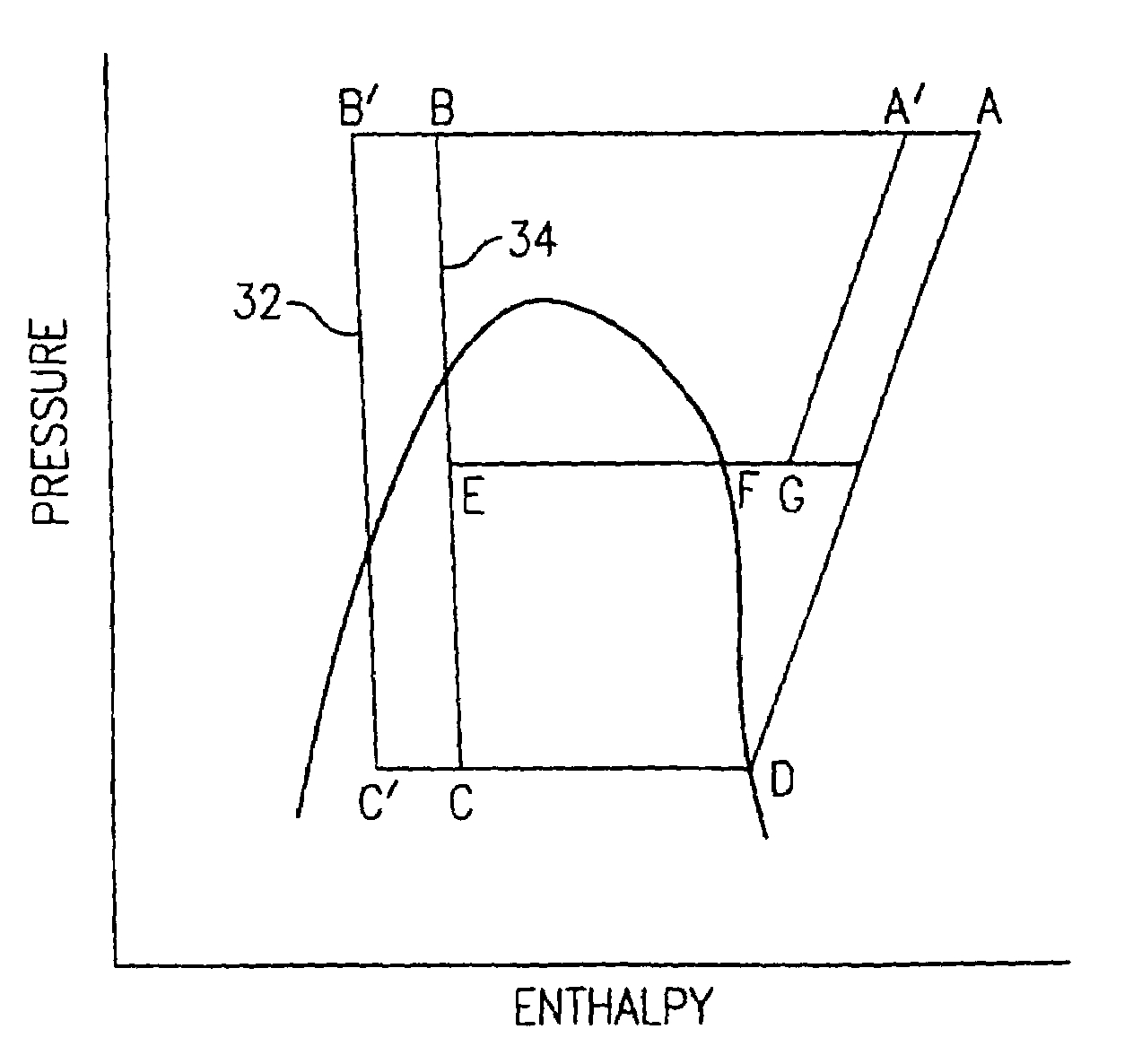
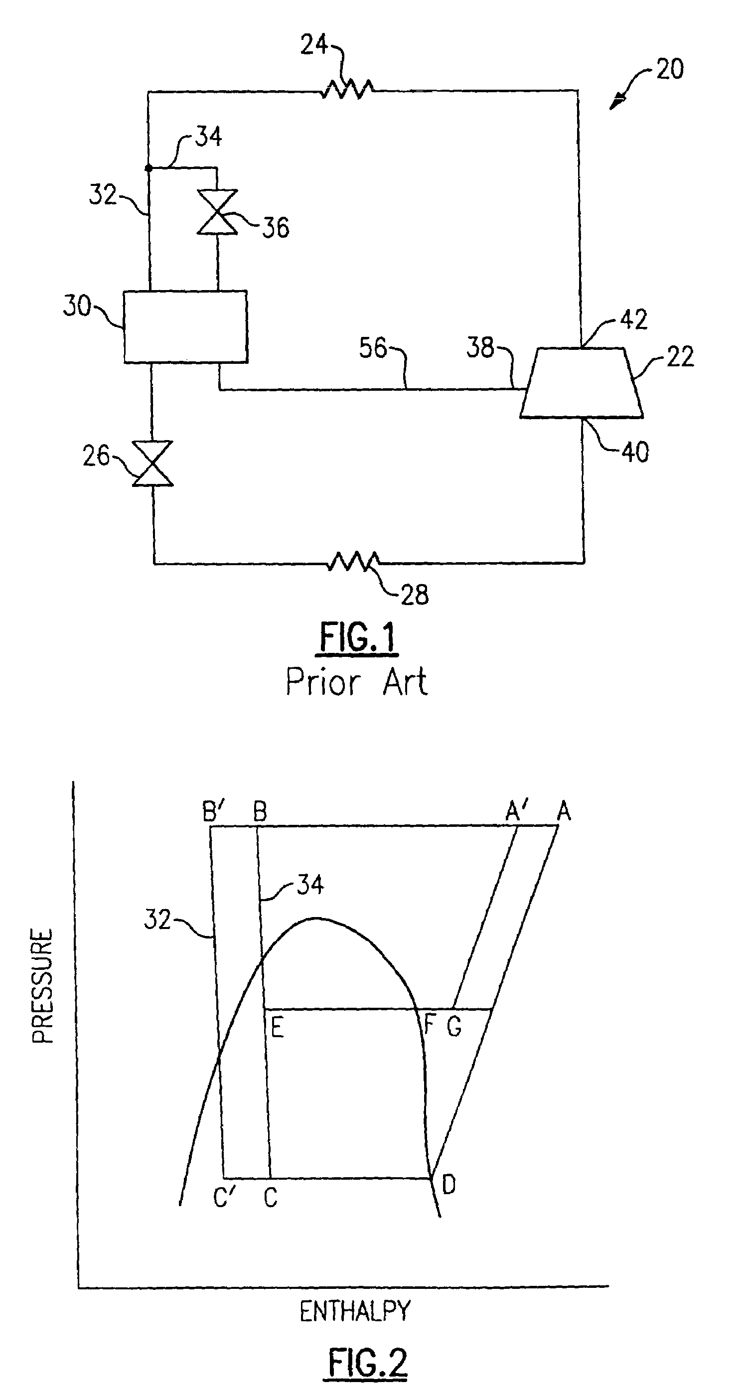
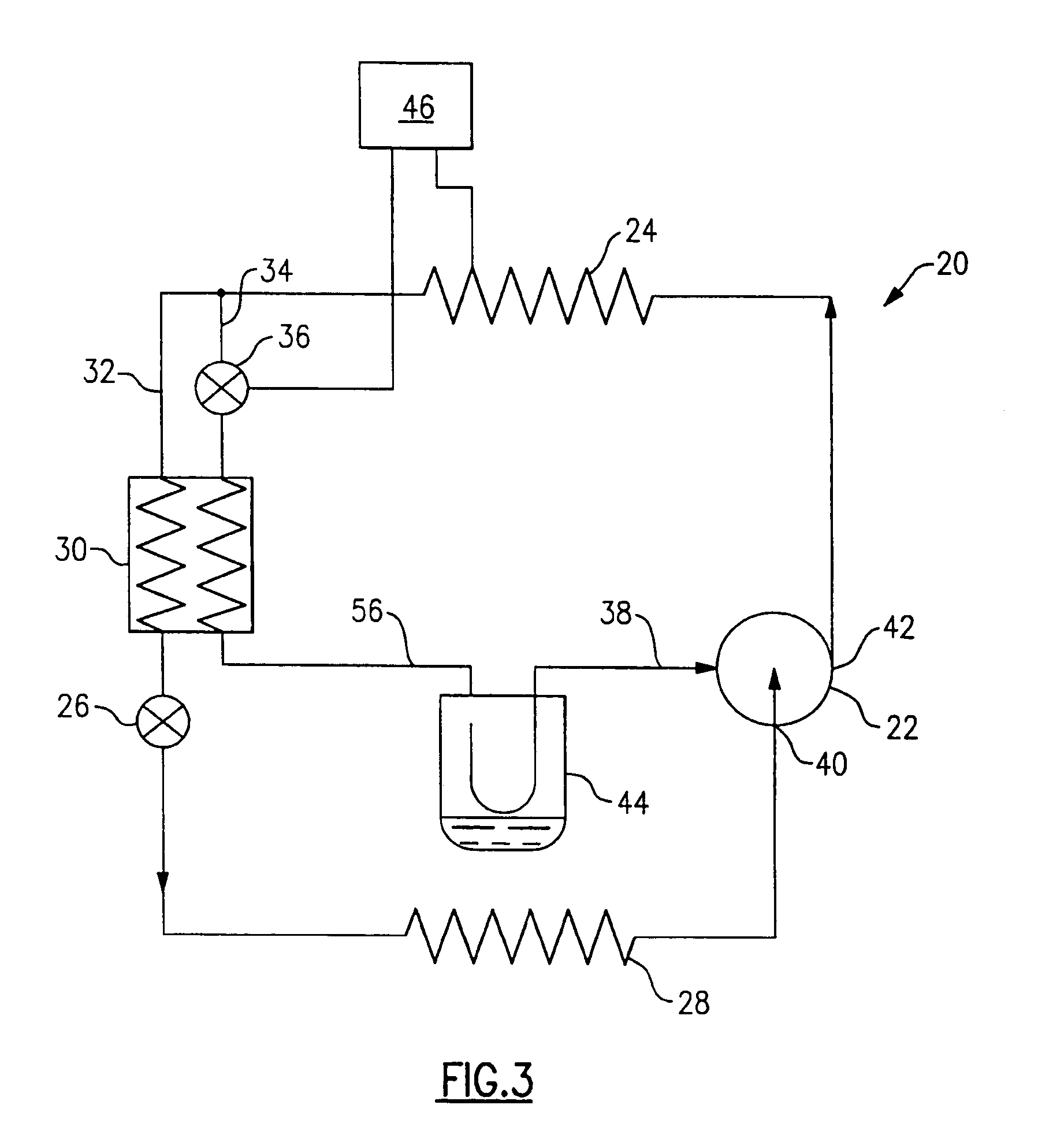
[0013]FIG. 1 schematically illustrates a prior art economized refrigeration system 20. The system 20 includes a compressor 22, a heat rejecting heat exchanger 24 (a gas cooler in transcritical cycles), a main expansion device 26, a heat accepting heat exchanger 28 (an evaporator), and an economizer heat exchanger 30. Refrigerant circulates though the closed circuit system 20. Refrigerant exits the compressor 22 through a discharge port 42 at high pressure and enthalpy. The refrigerant flows through the gas cooler 24 and loses heat, exiting at lower enthalpy and high pressure. The refrigerant then splits into two flow paths 32 and 34. Refrigerant in the economizer flow path 34 is expanded to a low pressure in an economizer expansion device 36 and exchanges heat with refrigerant in the main flow path 32 in the economizer heat exchanger 30, cooling the refrigerant in the main flow path 32. Refrigerant in the economizer flow path 34 is returned along the economizer return path 56 to the...


PUM


Abstract

Refrigerant is circulated through an economized refrigeration system including a compressor, a gas cooler, a main expansion device, an economizer heat exchanger and an evaporator. After cooling, the refrigerant splits into an economizer flow path and a main flow path. Refrigerant in the economizer flow path is expanded to a low pressure and exchanges heat with the refrigerant in the main flow path in the economizer heat exchanger. The refrigerant in the main flow path is then expanded and heated in the evaporator and enters the compressor, completing the cycle. An accumulator positioned between the economizer heat exchanger and the compressor stores excess refrigerant in the system, regulating the amount of refrigerant in the system and the high pressure in the system. The amount of refrigerant in the accumulator is controlled by regulating the economizer expansion device. By adjusting the amount of refrigerant in the accumulator, the amount of refrigerant in the system, and therefore the high pressure of the system, can be regulated.

Description

BACKGROUND OF THE INVENTION[0001]The present invention relates generally to a system for regulating the high pressure component of an economized refrigeration system by regulating the amount of refrigerant in the high pressure component of the system with an interstage accumulator positioned between an economizer heat exchanger and a compressor.[0002]Chlorine containing refrigerants have been phased out in most of the world due to their ozone destroying potential. Hydrofluoro carbons (HFCs) have been used as replacement refrigerants, but these refrigerants still have high global warming potential. “Natural” refrigerants, such as carbon dioxide and propane, have been proposed as replacement fluids. Unfortunately, there are problems with the use of many of these fluids as well. Carbon dioxide has a low critical point, which causes most air conditioning systems utilizing carbon dioxide to run partially above the critical point, or to run transcritical, under most conditions. The pressu...

Claims


Application Information

Patent Timeline
Patent Type & Authority Patents(United States)
IPC IPC(8): F25B41/00F25B5/00F25B9/00F25B43/00
CPCF25B9/008F25B1/10F25B43/006F25B2309/061F25B2700/19F25B2400/16F25B2600/17F25B2600/2501F25B2600/2509F25B2400/13F25B9/00F25B1/00F25B43/00
Inventor SIENEL, TOBIAS H.
Owner CARRIER CORP
Why Eureka
Try Eureka