Air-conditioning unit with additional heat transfer unit in the refrigerant circuit

a technology of air-conditioning unit and refrigerant circuit, which is applied in the direction of machine operation, light and heating apparatus, transportation and packaging, etc., can solve the problems of spontaneous high heat output, low heat output, and insufficient heat output of coolant, so as to increase the amount of heat passed and quickly warm the internal combustion engine. , the effect of not affecting the performance of the internal combustion engin

Inactive Publication Date: 2005-06-28
ROBERT BOSCH GMBH
View PDF13 Cites 31 Cited by
  • Summary
  • Abstract
  • Description
  • Claims
  • Application Information

AI Technical Summary

Benefits of technology

[0010]According to the invention, a coupled heat exchanger is located in the refrigerant circuit on the pressure side of the compressor upstream of the gas cooler, a first by-pass line is provided parallel to the gas cooler, and the flow through the gas cooler and the first by-pass line is controlled by a switching valve in the first by-pass line and one switching valve each located at the inlet and outlet of the gas cooler, depending on operating parameters. In addition, a heat transfer unit for a medium in a unit in the refrigerant circuit is connected downstream of an expansion valve and serves as heat source in heating operation.
[0011]With the air-conditioning unit according to the invention, the refrigerant flows through the expansion device and the evaporator in the same direction in heating operation and cooling operation. In heating operation, the air-conditioning unit functions as heat pump, and the heat transfer unit downstream of the expansion valve serves as heat source. The heat transfer unit cools a medium in a unit, e.g., the boost air of the internal combustion engine or the lube-oil of the internal combustion engine or a gearbox. Downstream of the heat transfer unit, the compressor compresses the pre-warmed refrigerant to a permissible final compression temperature. The heat produced as a result is given off by the coupled heat exchanger to the coolant in the coolant circuit, in fact, in advantageous fashion in the vicinity of a heating heat exchanger for the passenger compartment between the internal combustion engine and the heating heat exchanger. As a result, a large amount of heat can be passed to the coolant and utilized—without any notable delay or losses—to heat the passenger compartment and rapidly warm the internal combustion engine up to an optimal operating temperature.
[0012]To increase the amount of heat passed to the coolant when necessary, a hot-gas valve is provided as an option in the refrigerant circuit upstream of the coupled heat exchanger. As a result of this, the back-pressure reaction of the compressor can be increased so that it outputs more heat. Additionally, the refrigerant is expanded by the hot-gas valve to a permissible maximum pressure in the coupled heat exchanger.
[0013]In the heating operation, the compressor pumps the refrigerant to the evaporator, by-passing the gas cooler. In a cooling operation, the compressor pumps the refrigerant through the gas cooler to the evaporator. For this reason, the refrigerant circuit comprises a by-pass line parallel to the gas cooler, in which a switching valve serving as shutoff device is located. W...

Problems solved by technology

The use of internal combustion engines that are optimized in terms of fuel consumption in motor vehicles also affects the climate control of said motor vehicles by the fact that, in certain operating ranges, e.g., during the starting phase when outside temperatures are low, the amount of heat given off to the coolant is not sufficient to comfortably heat the motor vehicle.
This consumes minimal energy and responds spontaneously with high heat output.
A substantial disadvantage of a heat pump of this nature, however, is the fact that t...

Method used


Image

  • Air-conditioning unit with additional heat transfer unit in the refrigerant circuit
  • Air-conditioning unit with additional heat transfer unit in the refrigerant circuit
  • Air-conditioning unit with additional heat transfer unit in the refrigerant circuit

Examples


Embodiment Construction

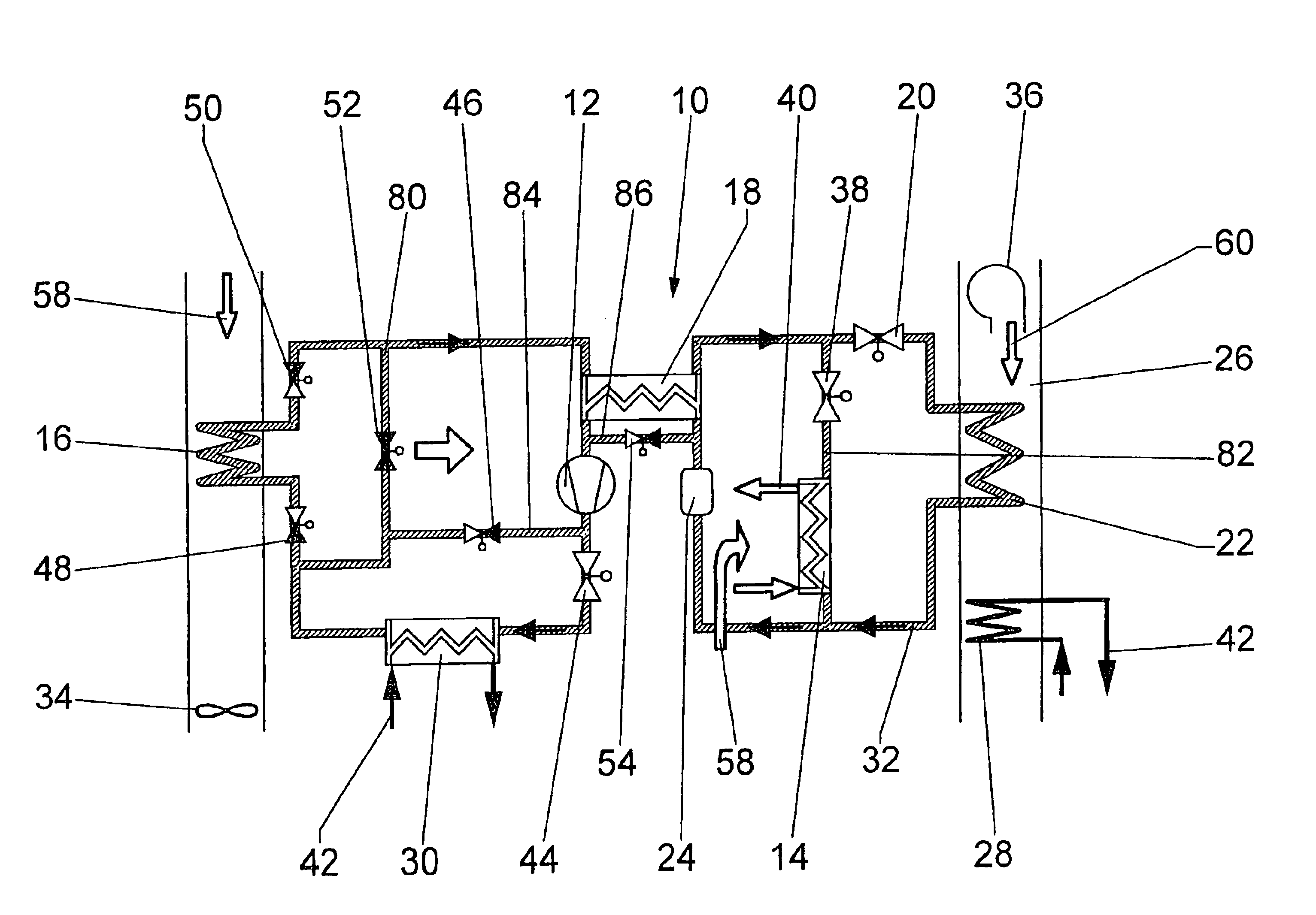
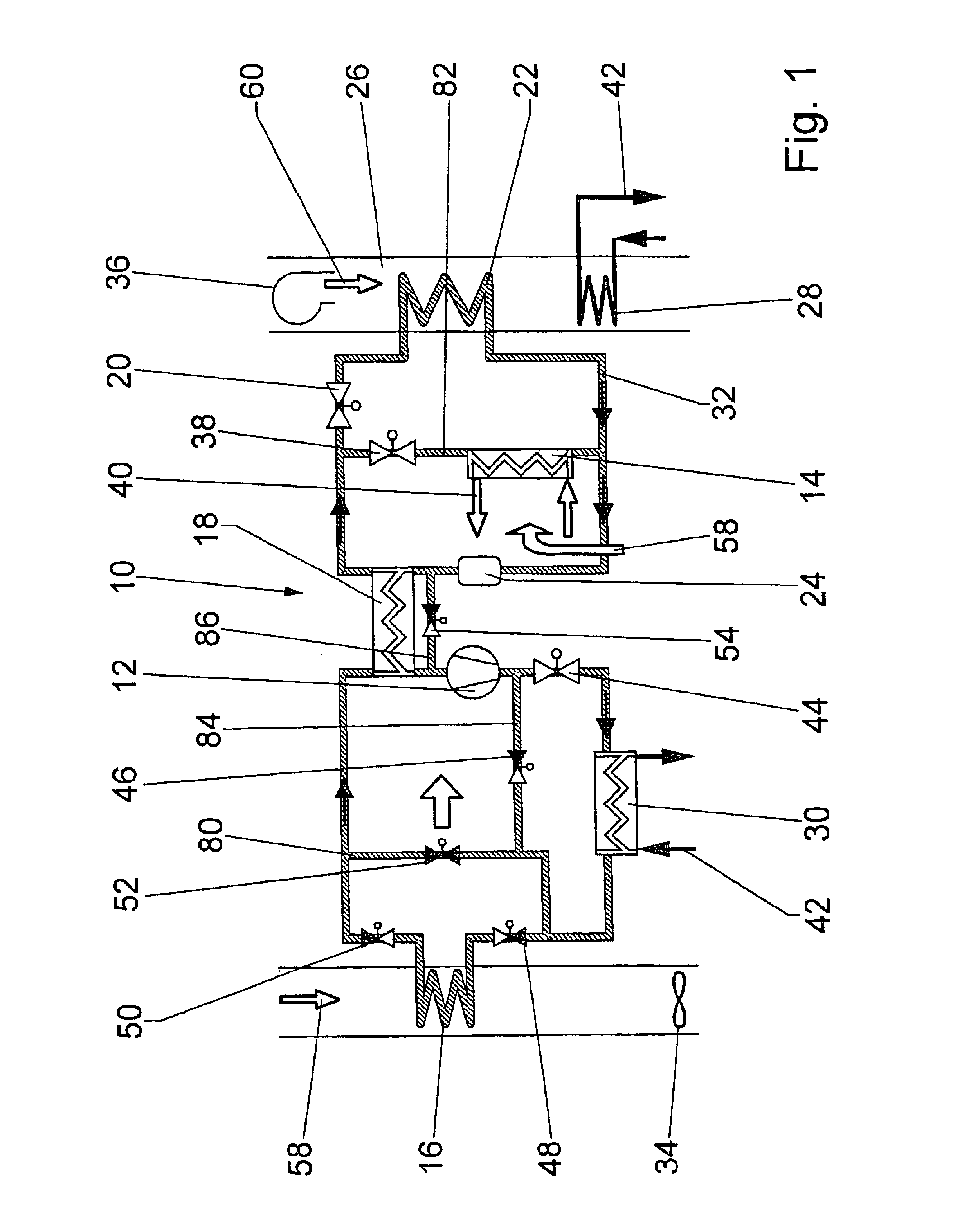
[0025]An air-conditioning unit 10 comprises a refrigerant line 32 in which a refrigerant, preferably carbon dioxide, circulates, and forms a closed refrigerant circuit. The course of flow of the refrigerant is indicated by arrows (FIG. 1). At low temperatures, the air-conditioning unit 10 is used as a heat pump by running it in a “heating operation”.

[0026]To heat the motor vehicle, a fan 36 draws in air 60 as fresh air from the environment or as recirculated air from the passenger compartment. Said air is pumped through an air-conditioning device 26 with an evaporator 22. The air 60 is dehumidified. A heating heat transfer unit 28 located downstream warms the air 60 to the desired temperature. The heating heat transfer unit 28 is connected to a coolant circuit 42 with a circulating coolant. In some operating ranges of the internal combustion engine in which the heat from the coolant is not sufficient to heat the passenger compartment, e.g., during the starting phase of the internal ...


PUM


Abstract

The invention relates to an air-conditioning unit (10) for a motor vehicle with a heating heat transfer unit (28) connected to a coolant circuit (42) in an internal combustion engine and comprising an evaporator (22) installed upstream in the direction of flow of a fan (36). A compressor (12) in a refrigerant circuit (32) pumps a refrigerant through a gas cooler (16) and an expansion valve (20) during a cooling operation, and pumps said refrigerant to the evaporator (22) via the expansion valve (20) by by-passing the gas cooler (16) during a heating operation. A coupled heat exchanger (30) is provided between the coolant circuit (42) and the refrigerant circuit (32). The invention provides that the coupled heat exchanger (30) is located in the refrigerant circuit (32) on the pressure side of the compressor (12) upstream of the gas cooler (16), a first by-pass line (80) is provided parallel to the gas cooler (16) and the flow through the gas cooler (16) and the first by-pass line (80) is controlled by a switching valve (52) in the first by-pass line (80) and a switching valve (48, 50) located at each of the inlet and outlet of the gas cooler (16), depending on operating parameters, and a heat transfer unit (14) for a medium in a unit in the refrigerant circuit (32) is connected behind an expansion valve (20 or 38) and serves as heat source in heating operation.

Description

BACKGROUND OF THE INVENTION[0001]The invention relates to an air-conditioning unit according to the preamble of claim 1.[0002]The use of internal combustion engines that are optimized in terms of fuel consumption in motor vehicles also affects the climate control of said motor vehicles by the fact that, in certain operating ranges, e.g., during the starting phase when outside temperatures are low, the amount of heat given off to the coolant is not sufficient to comfortably heat the motor vehicle. Auxiliary heating units are therefore required in order to ensure comfort at low temperatures and to enable deicing of the vehicle windows, if necessary. An air-conditioning unit can also serve as auxiliary heating unit, especially since an increasing number of motor vehicles are being equipped with an air-conditioning unit as a standard feature. At low temperatures, the air-conditioning unit is used as a heat pump by reversing the flow of refrigerant. This consumes minimal energy and respo...

Claims


Application Information

Patent Timeline
IPC IPC(8): B60H1/00F25B9/00F25B40/00B60H1/22F25B1/00
CPCB60H1/00314B60H1/00899F25B9/008F25B40/00B60H2001/00942B60H2001/00949F25B2600/2501F25B2309/061B60H2001/00957
Inventor HORSTMANN, PETERLEUTHNER, STEPHANSATZGER, PETERMALL, GERNOTKANTERS, PETRA
Owner ROBERT BOSCH GMBH
Why Eureka
Try Eureka