Transcritical vapor compression optimization through maximization of heating capacity

a technology of vapor compression system and heating capacity, applied in the field of system and method of optimizing a transcritical vapor compression system, can solve the problems of oversized vapor compression system to achieve sufficient heating capacity, insensitive to high performance, and inconvenient operation, so as to achieve the effect of optimizing the heating capacity of the system

Active Publication Date: 2006-05-30
CARRIER CORP
View PDF17 Cites 30 Cited by
  • Summary
  • Abstract
  • Description
  • Claims
  • Application Information

AI Technical Summary

Problems solved by technology

Chlorine containing refrigerants have been phased out in most of the world due to their ozone destroying potential.
However, the coefficient of performance becomes insensitive to the high side pressure when the high side pressure of the system is set above the optimal high side pressure.
In prior vapor compressions systems, the vapor compression system is oversized to achieve sufficient heating capacity in low ambient conditions.
A drawback to oversizing a vapor compression system is that it is expensive and requires more space.

Method used


Image

  • Transcritical vapor compression optimization through maximization of heating capacity
  • Transcritical vapor compression optimization through maximization of heating capacity
  • Transcritical vapor compression optimization through maximization of heating capacity

Examples


first embodiment

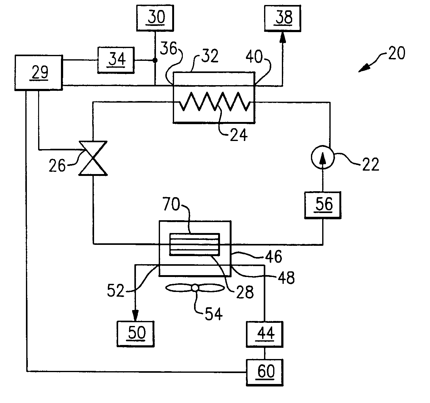
[0028]FIG. 3 illustrates the present invention. The optimal heating capacity of the vapor compression system 20 is determined by measuring the current required to operate the water pump 34. The water pump 34 pumps the cooled fluid medium 30 through the gas cooler 24 at a flowrate. In the gas cooler 24, the cooled fluid medium 30 accepts heat from the refrigerant exiting the compressor 22. The higher the current required to operate the water pump 34, the higher the flowrate of cooled fluid medium 30 by the water pump 34, the higher the heat transfer between the fluid medium 30 and the refrigerant in the gas cooler 24, and the higher the heating capacity. That is, as the current to operate the water pump 34 increases, the system heating capacity increases.

[0029]A controller 29 regulates the system 20. At a given high side pressure, the heating capacity can be calculated based on the current measured to operate the water pump 34. The controller 29 stores the calculated heating capacity...

second embodiment

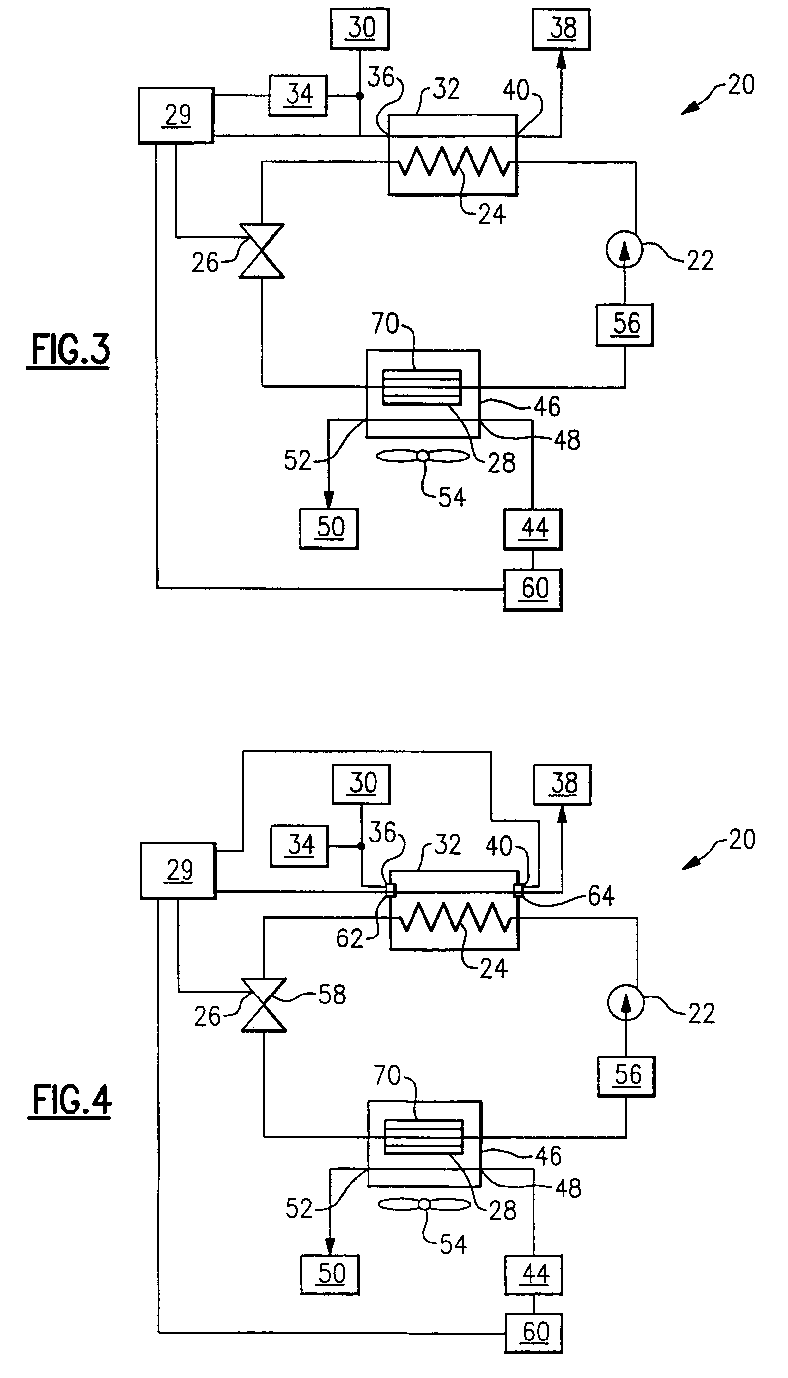
[0031]FIG. 4 illustrates the present invention. Three system characteristics are measured to determine the optimal system heating capacity pressure P2. A water inlet temperature sensor 62 detects a water inlet temperature of the fluid medium 30 entering the gas cooler 24, a water outlet temperature sensor 64 detects a water outlet temperature of the water 38 exiting the gas cooler 24, and an ambient air temperature sensor 60 detects a heated fluid medium temperature, which in this example is an ambient air 44 temperature. The three temperatures detected by sensors 60, 62, and 64 are communicated to and collected by the controller 29.

[0032]Optimal high side pressure values for various temperatures are programmed and stored in the controller 29. Based on the detected temperatures, an optimal high side pressure is determined. Alternately, the optimal size or percentage of the orifice of the expansion device 26 is determined based on the detected temperatures. Alternately, the control c...


PUM


Abstract

A vapor compression system includes a compressor, a gas cooler, an expansion device, and an evaporator. Refrigerant is circulated through the system. The high side pressure of the vapor compression system is selected to optimize the heating capacity. In one example, the optimal high side pressure is obtained by determining the high side pressure that correlates to the maximum current required to operate to the water pump. In another example, the actual temperature of the water entering the gas cooler, the water exiting the gas cooler, and the ambient air temperature are measured and compared to a predetermined value to determine the optimal high side pressure.

Description

BACKGROUND OF THE INVENTION[0001]The present invention relates generally to a system and method of optimizing a transcritical vapor compression system by maximizing the system heating capacity.[0002]Chlorine containing refrigerants have been phased out in most of the world due to their ozone destroying potential. Hydrofluorocarbons (HFCs) have been used as replacement refrigerants, but these refrigerants still have high global warming potential.[0003]“Natural” refrigerants, such as carbon dioxide and propane, have been proposed as replacement fluids. Carbon dioxide can be used as a refrigerant in automotive air conditioning systems and other heating and cooling applications. Carbon dioxide has a low critical point, which causes most air conditioning systems utilizing carbon dioxide as a refrigerant to run transcritically, or partially above the critical point, under most conditions.[0004]A vapor compression system must be able to provide enough heating capacity to meet the load requ...

Claims


Application Information

Patent Timeline
Patent Type & Authority Patents(United States)
IPC IPC(8): F25B13/00F25B41/04F25D17/00F25B9/00F25B30/02
CPCF25B9/008F25B30/02F25B2309/061F25B2700/21161F25B2600/17F25B2700/2106F25B2339/047
Inventor CHEN, YUSIENEL, TOBIAS H.ZHANG, LILI
Owner CARRIER CORP
Why Eureka
Try Eureka