
Method and system for detecting and displaying the impact of a blow

a technology of blows and impact indicators, applied in the field of sports equipment, can solve the problems of difficult to judge from the angle and distance of judges whether the blow is of sufficient impact to be scored, and the difficulty of judges accurately and consistently performing, etc., to achieve the effect of light weigh

Inactive Publication Date: 2005-08-09
SENSORPAD SYST
View PDF30 Cites 97 Cited by
  • Summary
  • Abstract
  • Description
  • Claims
  • Application Information

AI Technical Summary

Benefits of technology

[0015]These methods and systems overcome the disadvantages of the prior art. The sensor and transmitter units of the invention are light in weight and employ thin, conformable sensors that do not appreciably...

Problems solved by technology

With specific reference to number of blows landed, three factors render it difficult for judges to accurately and consistently perform this task: 1) The speed of the matches makes it relatively easy to miscount the number of blows; 2) A judge may not be able to see some of the action clearly because of obstruction by the bodies of the boxers or the referee; 3) Even when blows are clearly seen, it is difficult to judge from the angle and distance of the judges whether the blow is of sufficient impact to be scored.
As a result, the scoring by different judges, as well as by the press and other observers can disagree, resulting in controversy over the outcome of a match.
The appeal of boxing as entertainment has waned in recent years, and the audience for boxing continues to age.
Carlin does not measure force directly, and the addition of such equipment is not likely to be acceptable to boxers, and indeed may represent a safety risk to the boxers.

Method used


Image

  • Method and system for detecting and displaying the impact of a blow
  • Method and system for detecting and displaying the impact of a blow
  • Method and system for detecting and displaying the impact of a blow

Examples


Embodiment Construction

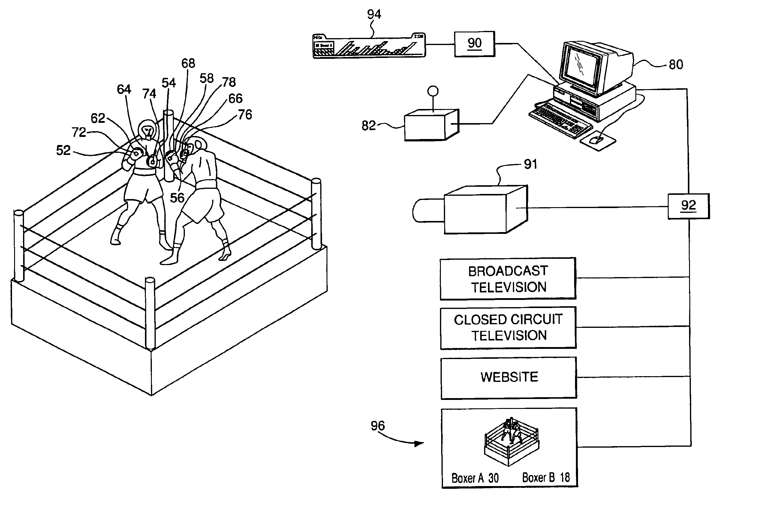
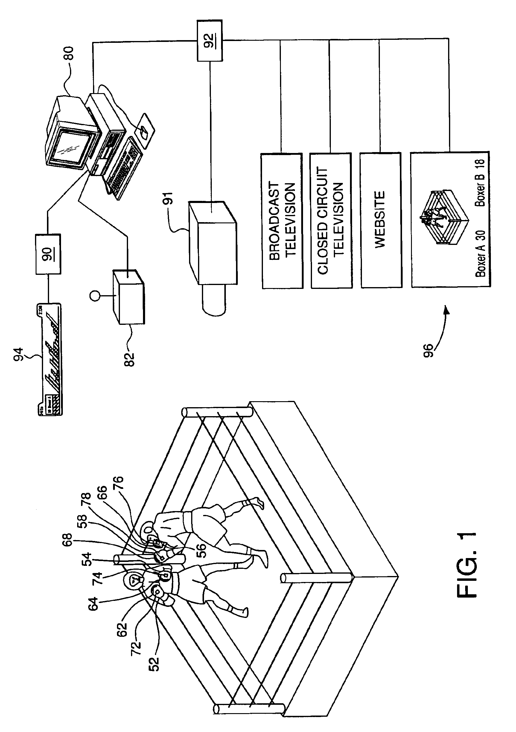
[0028]The system of the invention includes components in an article of athletic equipment, including a sensor, a circuit and a transmitter, and components external, including a receiver, data processor, and various display technology. The method of the invention includes processes carried out within an article of athletic equipments, as well as processes carried out in connection with the transmission, analysis, storage and display of data representing forces and numbers of hits detected on an article of athletic equipment. FIG. 1 is a schematic overview of a system of the invention for use in multiple items of athletic equipment, specifically in the context of a boxing match. A boxing match is shown. The two boxers each have a pair of boxing gloves; these are boxing gloves 52, 54, of a first boxer, and boxing gloves 56, 58 of a second boxer. Each boxing glove has therein a force sensor positioned in a portion of glove selected to receive a blow. Each boxing glove has one of sending...


PUM


Abstract

A system for detecting and displaying force data relating to impacts received on an item of athletic equipment includes two or more items of athletic equipment each having a force sensor, logic and a wireless transmitter therein, a receiver adapted to receiver signals from each of the transmitters, and a processor for formatting the data for display. The force sensor may be a capacitive force sensor. The logic may have an operating mode and a sleep mode, with an inertial sensor providing a signal to cause the logic to switch from sleep mode to operating mode. The logic identifies and stores signals exceeding a threshold for transmission. Transmissions are repeated, and the receiver is adapted to distinguish and discard corrupted and repeated transmissions. The display provides an indication of force and number of recorded hits in association with the names of the competitors. The athletic equipment may be boxing gloves, and the force and number of hit data may be provided simultaneously with images and commentary for a boxing match. The data may be displayed as a standalone graphic or superimposed over an image of a match.

Description

RELATED APPLICATIONS[0001]This application claims priority from U.S. Provisional Patent Application No. 60 / 351,626, filed Jan. 24, 2002, which application is hereby incorporated by reference herein in its entirety.FIELD OF THE INVENTION[0002]This invention relates to sports equipment, particularly boxing equipment and equipment for use in martial arts, and to broadcasts of sporting events, particularly boxing matches.BACKGROUND OF THE INVENTION[0003]The determination of the force of a blow is of interest in a variety of athletic competitions and training contexts. For example, in professional boxing matches there are four criteria used for scoring: effective aggressiveness, command of the ring, defense and number of blows landed. With specific reference to number of blows landed, three factors render it difficult for judges to accurately and consistently perform this task: 1) The speed of the matches makes it relatively easy to miscount the number of blows; 2) A judge may not be abl...

Claims


Application Information

Patent Timeline
IPC IPC(8): A63B69/32A63B69/34A63B69/20G01N3/303G01N3/307G01N3/30G01N3/31G01N3/313G01N3/317G01N3/00A63B24/00A63B69/00A63B71/12A63B71/14G01L1/14G01M7/00G09GG09G1/00
CPCA63B69/32A63B71/06A63B69/004A63B71/1225A63B71/145A63B2071/065A63B2208/12A63B2220/53A63B2220/803A63B2225/50A63B2230/50A63B2244/102
Inventor REINBOLD, KIRK A.GOLDMAN, ROBERT J.LYNGARD, BARRYEBERHARDT, SILVIOMICHEL, PETERAUGUSTINE, JR., ALBERT
Owner SENSORPAD SYST
Learn More