Heat dissipation device

a heat dissipation device and heat dissipation technology, which is applied in the direction of lighting and heating apparatus, semiconductor/solid-state device details, laminated elements, etc., can solve the problems of abnormal operation or damage, large heat generation, and limited height of the fins, and achieve great heat dissipation efficiency

Inactive Publication Date: 2005-08-09
HON HAI PRECISION IND CO LTD
View PDF12 Cites 23 Cited by
  • Summary
  • Abstract
  • Description
  • Claims
  • Application Information

AI Technical Summary

Benefits of technology

[0008]Accordingly, an object of the present invention is to provide a heat dissipation device having a great heat dissipation efficiency.

Problems solved by technology

The fins are relatively thick in comparison with distances defined between each two adjacent fins, due to inherent limitations in extrusion technology This restricts the number of the fins that can be formed, and a total heat dissipation area that can be provided by the fins.
Furthermore, a height of the fins is limited to about 13 times the distance between each two adjacent fins, also due to inherent limitations in extrusion technology.
With the continuing boom in electronics technology, numerous modem electronic components such as central processing units (CPUs) of computers can operate at very high speeds and thus generate large amounts of heat.
The heat must be efficiently removed from the CPU; otherwise, abnormal operation or damage may result.
Conventional extruded heat dissipation devices are increasingly no longer able to adequately remove heat from these contemporary electronic components.
First, the fins 42 are relatively thin so that a mold for manufacturing the fins 42 is difficult to be made.
This design has less help to prompt heat dissipating capability.
The heat removal efficiency of the heat dissipation device is still low relative to the requirement of the contemporary electronic components.

Method used


Image

  • Heat dissipation device
  • Heat dissipation device
  • Heat dissipation device

Examples


Embodiment Construction

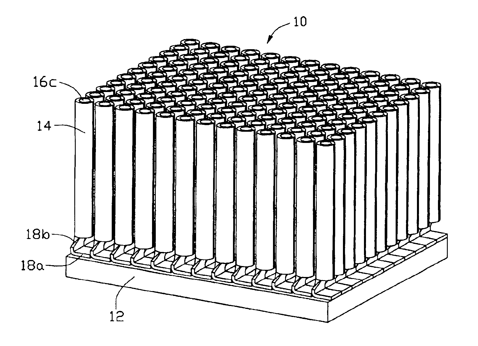
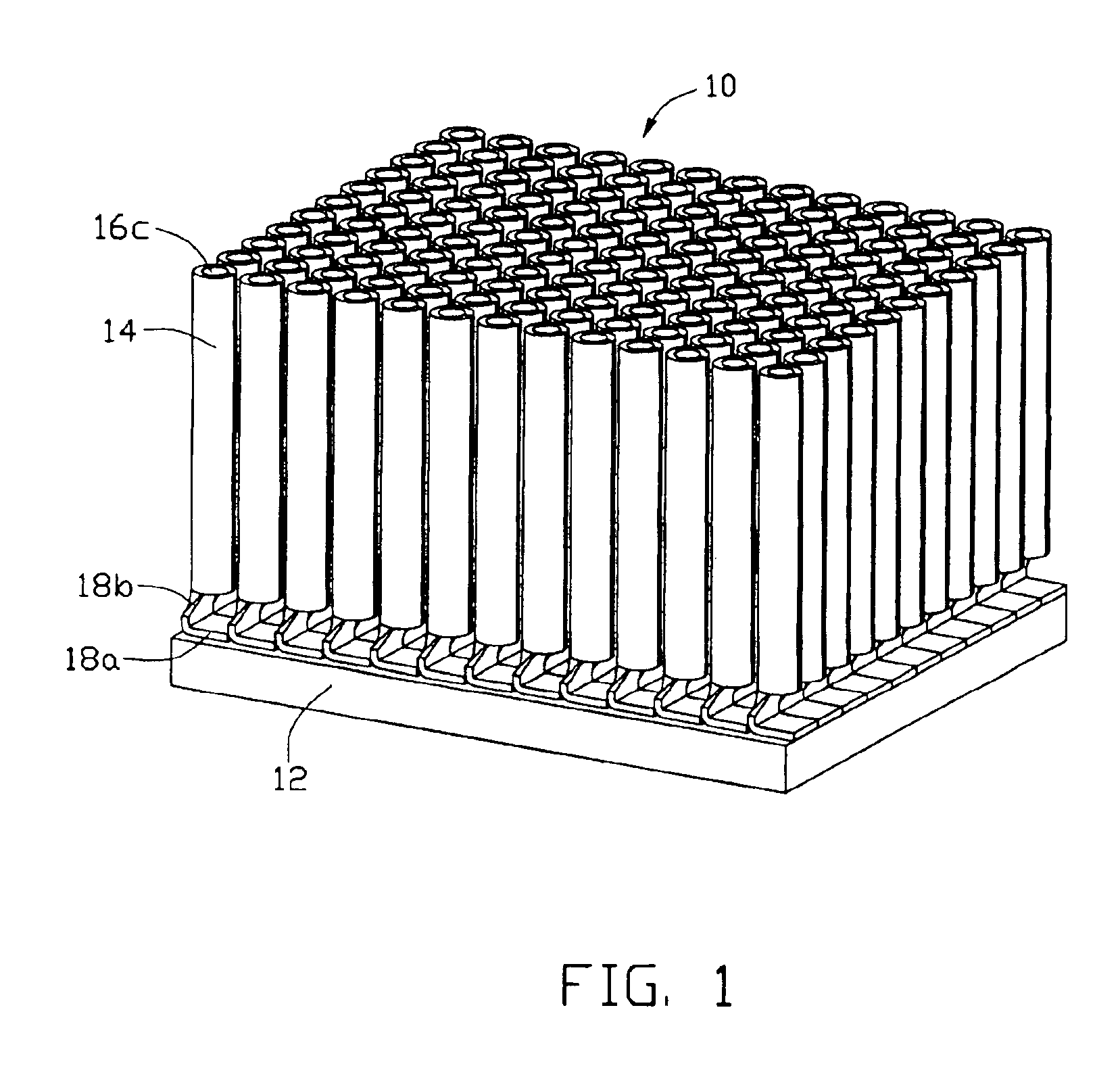
[0014]Referring to FIGS. 1-2, a heat dissipation device 10 in accordance with the preferred embodiment of the present invention comprises a base 12 for contacting an electronic component (not shown), and a plurality of individual fins 14. The base 12 is for removing heat from the electronic component. The fins 14 are attached to the base 12. In the preferred embodiment, the base 12 is flat.

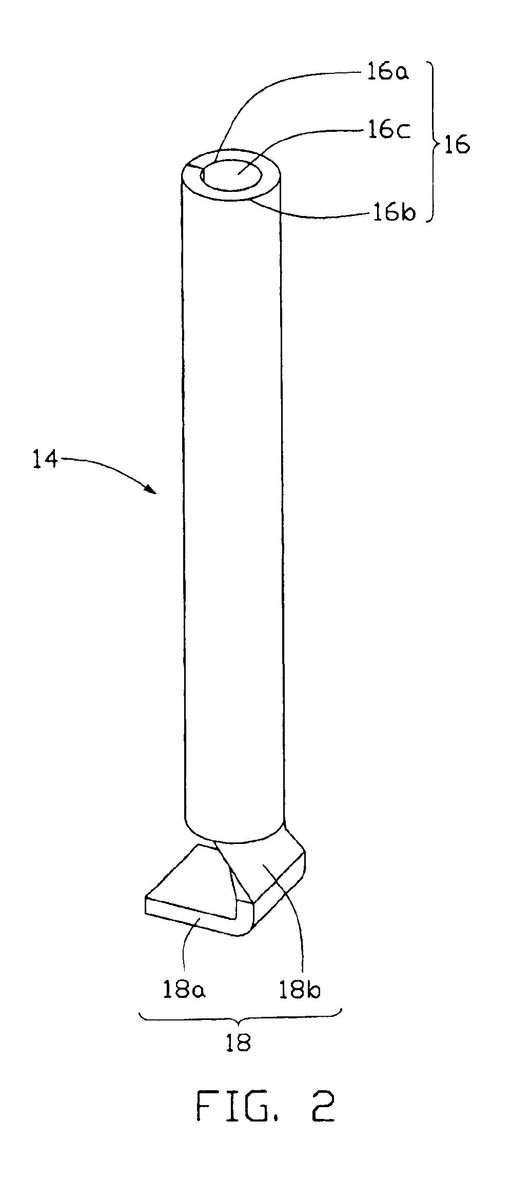
[0015]Each fin 14 is made from a metallic slice. Each fin 14 comprises a heat dissipating post 16 rolling up from a main body of the metallic slice and a heat conducting portion 18 extending from the main body of the metallic slice. The heat dissipating post 16 is substantially a hollow post and comprises a first heat dissipating surface 16a and a second heat dissipating surface 16b, and further defines an axile through hole 16c by the first heat dissipating surface 16a. The heat conducting tab 18 comprises an engaging part 18a for engaging with the base 12 and a medial part 18b integrally extends...


PUM

PropertyMeasurementUnit
heat conductingaaaaaaaaaa
heataaaaaaaaaa
conductingaaaaaaaaaa

Abstract

A heat dissipation device (10) includes a base (12) and a plurality of fins (14). Each fin includes a heat dissipating post (14) and a heat conducting tab (18). Each heat dissipating post is made by rolling up a metallic slice and thereby defines a through hole therein. Each heat conducting tab includes an engaging part (18a) attached on the base and a medial part (18b) extending from the corresponding heat dissipating post. The medial parts thermally connect the engaging parts and the heat dissipating posts, and mechanically separate the engaging parts from the heat dissipating posts; thereby the through holes are allowed to be exposed at opposite ends of the heat dissipating posts.

Description

BACKGROUND OF THE INVENTION[0001]1. Field of the Invention[0002]The present invention relates to heat dissipation devices for removing heat from electronic components, and more particularly to a heat dissipation device combined by a base and a plurality of fins attached to the base.[0003]2. Description of Prior Art[0004]Conventional heat dissipation devices used for removing heat from electronic components are mostly formed by extrusion of metallic material. The heat dissipation device comprises a base, and a plurality of fins integrally extending from the base. The fins are relatively thick in comparison with distances defined between each two adjacent fins, due to inherent limitations in extrusion technology This restricts the number of the fins that can be formed, and a total heat dissipation area that can be provided by the fins. Furthermore, a height of the fins is limited to about 13 times the distance between each two adjacent fins, also due to inherent limitations in extrusi...

Claims


Application Information

Patent Timeline
Patent Type & Authority Patents(United States)
IPC IPC(8): B21D53/02F28F3/00F28F3/02H01L23/367H01L23/34
CPCB21D53/02F28F3/02H01L23/3677Y10T29/4935H01L2924/0002H01L2924/00F28F2215/06
Inventor LEE, HSIEH KUNLU, CUIJUN
Owner HON HAI PRECISION IND CO LTD
Why Eureka
Try Eureka