Method and device for detecting touch pad unit

Inactive Publication Date: 2005-08-09
WSOU INVESTMENTS LLC
View PDF13 Cites 129 Cited by
  • Summary
  • Abstract
  • Description
  • Claims
  • Application Information

AI Technical Summary

Benefits of technology

[0018]It is further preferable to provide a compensation emitter, which is placed adjacent to the receiver and operated in a pulsed mode of the same frequency, but with a complementary phas

Problems solved by technology

When a user presses the pad, the layers are caused to make contact with each other at the pressing point, thereby interrupting the current in the electrode grid.
When the touch pad is also used as an information display or an image display, the electrodes positioned on top of a touch pad may affect the

Method used


Image

  • Method and device for detecting touch pad unit
  • Method and device for detecting touch pad unit
  • Method and device for detecting touch pad unit

Examples


Example

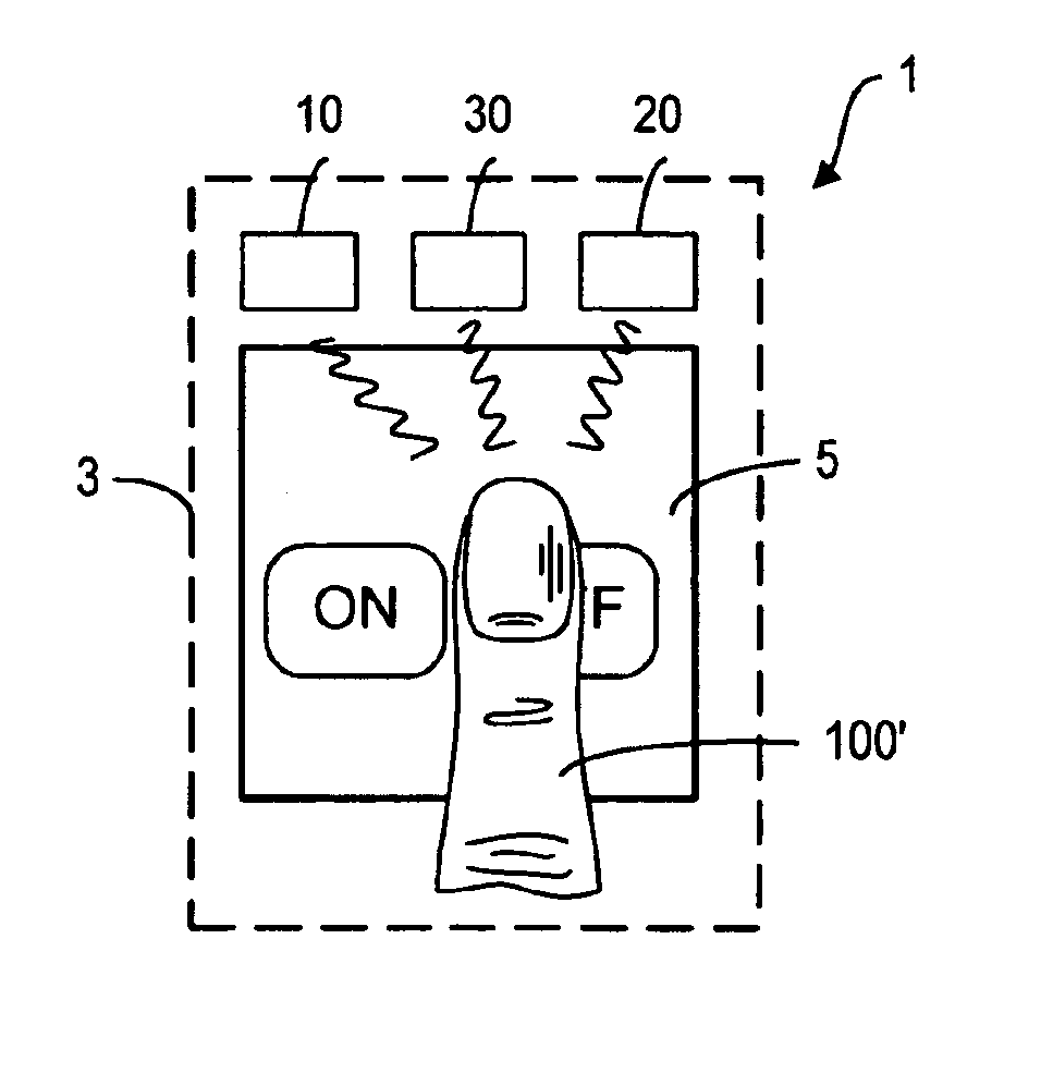
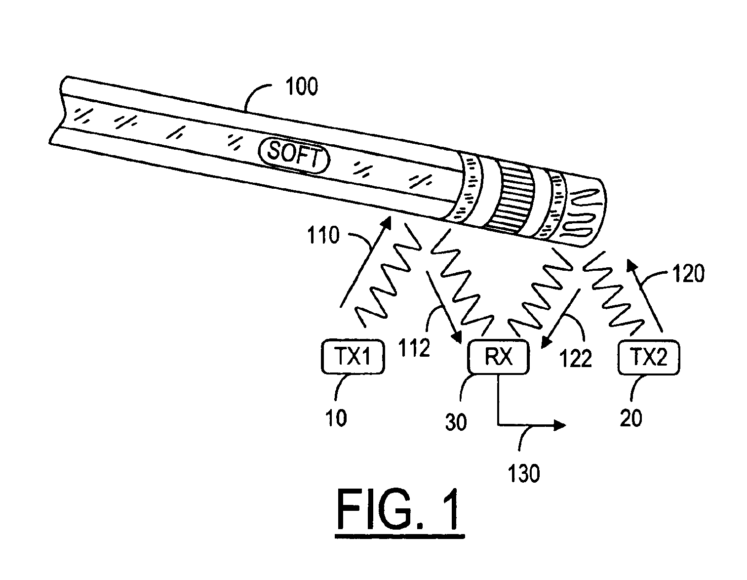
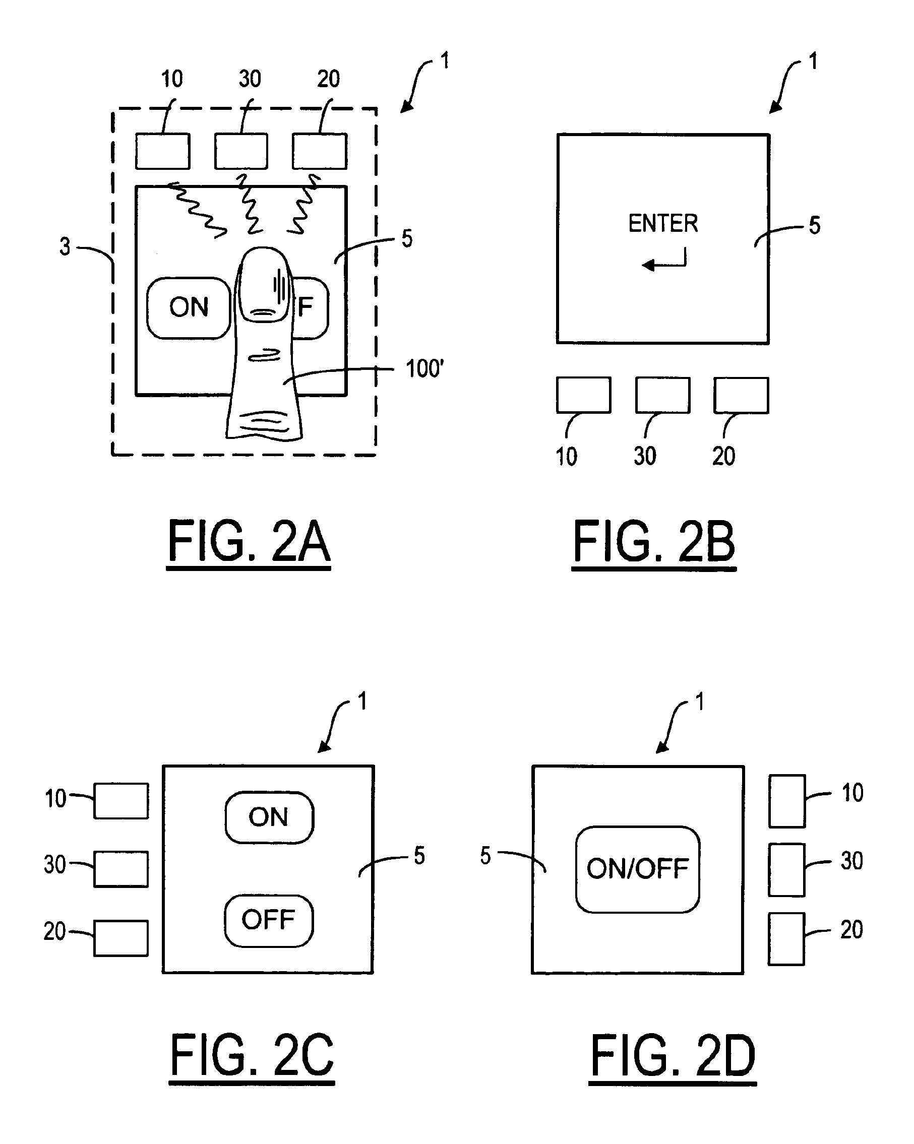
[0073]As shown in FIG. 1, two light emitters 10, 20 are positioned on opposite sides of a light receiver 30 in the proximity of a touch pad 5 (see FIGS. 2A-2D). When a user uses an object such as a pencil 100 or a finger 100′ (FIG. 2A) to touch the touch pad 5, some light 110 emitted from the emitter 10 encounters the surface of the object 100. Part of the light 110 reflects off the object 100 and is received by the receiver 30. Likewise, some light 120 emitted from the emitter 20 encounters the surface of the object 100 and then reflects off the object 100 to receiver 30. The received portions are denoted by reference numerals 112 and 122. The amount of light received by the receiver 30 can be measured from the output signal 130. If the receiver 30 is not already saturated by ambient light, the presence of the object 100 near the emitters 10, 20 and the receiver 30 would cause a change in the output signal 130. When such a change is detected, it is preferred that the change attribu...


PUM


Abstract

A method and system for detecting the presence of an object at a touch pad device, wherein the touch pad device has a designated interaction area for allowing a user to use the object to interact with the touch pad device for inputting one or more functions in an electronic device. One or more groups of optical sensor components, each including an optical receiver and two light emitters positioned at opposite sides of the receiver such that when an object is present at the touch pad device, the changes in the receiver output can be used to determine the location of the object as a function of time. Preferably, the light emitters are operated in a pulsed mode so that the changes in the receiver output contain a frequency component so as to distinguish the changes due to the presence of the object and those of ambient light.

Description

CROSS REFERENCE TO RELATED APPLICATIONS[0001]Reference is made to pending application Ser. No. 09 / 928,929 entitled METHOD AND SYSTEM FOR PREVENTING UNINTENDED TOUCH PAD INPUT DUE TO ACCIDENTAL TOUCHING, assigned to the assignee of the present invention and filed on even date herewith.FIELD OF THE INVENTION[0002]The present invention relates generally to a touch sensitive device in an electronic device or a wireless telecommunication terminal.BACKGROUND OF THE INVENTION[0003]A touch pad is usually defined as a touch-sensitive user interface area in an electronic device, which allows a user to input information or a command to the device by pressing the touch sensitive area. The touch pad can be used as a keypad having a designated functionality. For example, a touch pad can be used as an on / off switch and the user can turn the electronic device on or off by pressing the touch sensitive area. The touch pad can have several selectable functions. For example, the touch pad can be used a...

Claims


Application Information

Patent Timeline
IPC IPC(8): G06F3/033G06F3/042
CPCG06F3/03547G06F3/0421G06F2203/04109
Inventor REIME, GERDKAIKURANTA, TERHO
Owner WSOU INVESTMENTS LLC
Why Eureka
Try Eureka