Fire detector with electronic frequency analysis

a technology of electronic frequency analysis and fire detector, which is applied in the direction of optical radiation measurement, fire alarm radiation actuation, instruments, etc., can solve the problems of reducing the danger of fire from sparking or arcing is, in fact, quite serious, and the environment is fraught with fire hazards and safety concerns. , to achieve the effect of reducing or eliminating interruptions

Inactive Publication Date: 2005-08-09
HONEYWELL INT INC
View PDF32 Cites 13 Cited by
  • Summary
  • Abstract
  • Description
  • Claims
  • Application Information

AI Technical Summary

Benefits of technology

[0013]The present invention is directed in various aspects to a sensitive, reliable, intelligent and effective method and system for detecting sparks, flames or fire while reducing or eliminating interruptions caused by false alarms.

Problems solved by technology

While facilitating efficiency, environmental benefits, and many production advantages, electrostatic coating of parts in a production paint line, presents an environment fraught with fire hazards and safety concerns.
For example, sparks are common from improperly grounded workpieces or faulty spray guns.
In instances where the coating material is a paint having a volatile solvent, the danger of a fire from sparking, or arcing, is, in fact, quite serious.
Fires are also a possibility if electrical arcs occur between charged objects and a grounded conductor in the vicinity of flammable vapors.
An electrical spark can cause the paint (fuel) to exceed its ignition temperature.
The resulting spray gun fire can quickly produce radiant thermal energy sufficient to raise the temperature of the nearby paint residue on the booth walls or floor, causing the fire to quickly spread throughout the paint booth.
Thus, if the fuel supply of the fire is cut off, the fire typically stops.

Method used


Image

  • Fire detector with electronic frequency analysis
  • Fire detector with electronic frequency analysis
  • Fire detector with electronic frequency analysis

Examples


Embodiment Construction

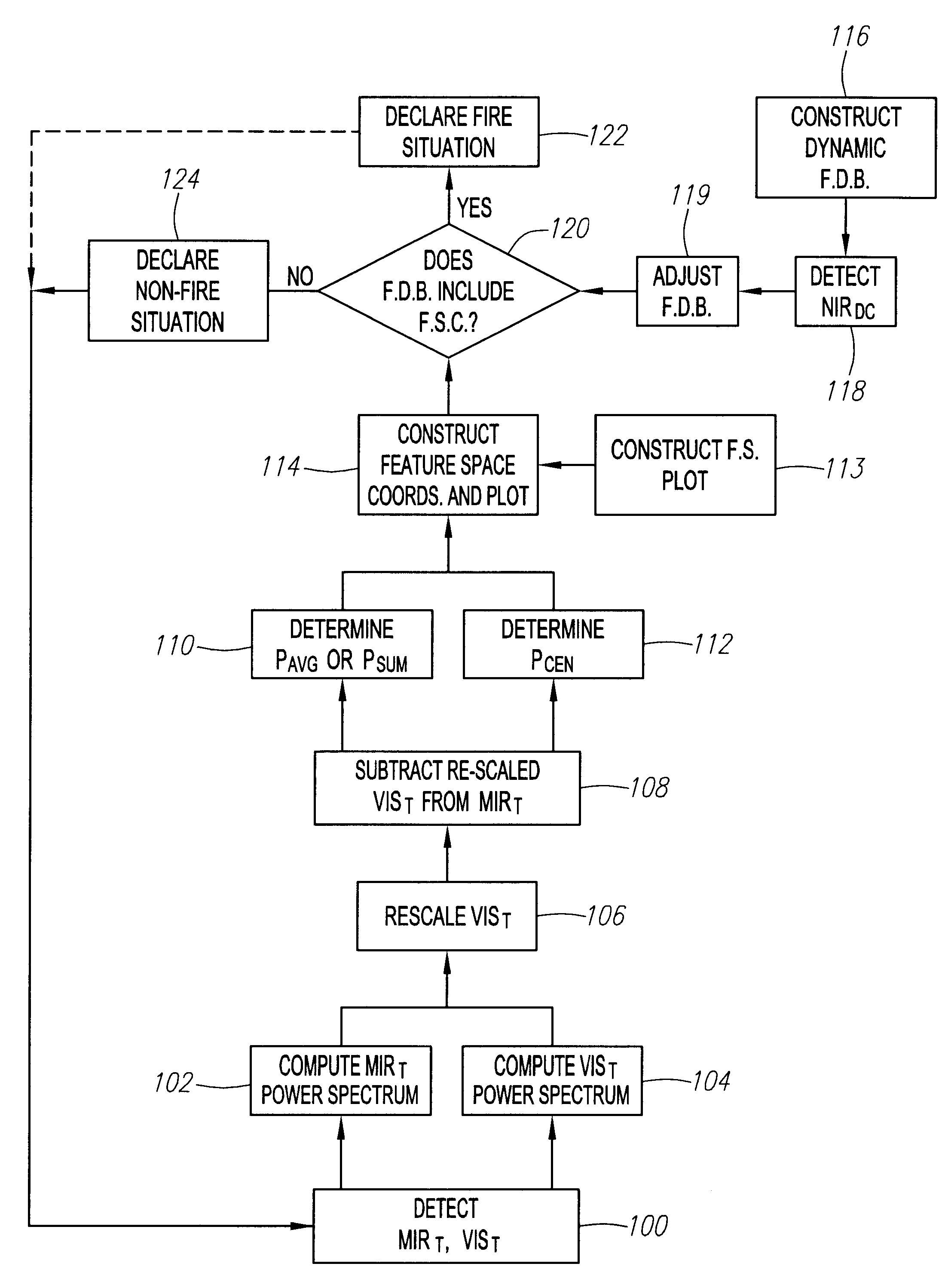
[0036]Processes and systems for detecting sparks, flames, or fire in accordance with preferred embodiments are described herein.

[0037]A particular embodiment of a process and system for fire detection is described in conjunction with an exemplary situation of an electrostatic coating operation. However, it should be understood that the process and system may be effectively utilized in any environment facing a threat from sparks, flames, or fire. For example, the process and system may be used in such applications as petrochemical facilities and refineries, semiconductor fabrication plants, co-generation plants, aircraft hangars, gas storage facilities, gas turbines and power plants, gas compressor stations, munitions plants, airbag manufacturing plants, and so on.

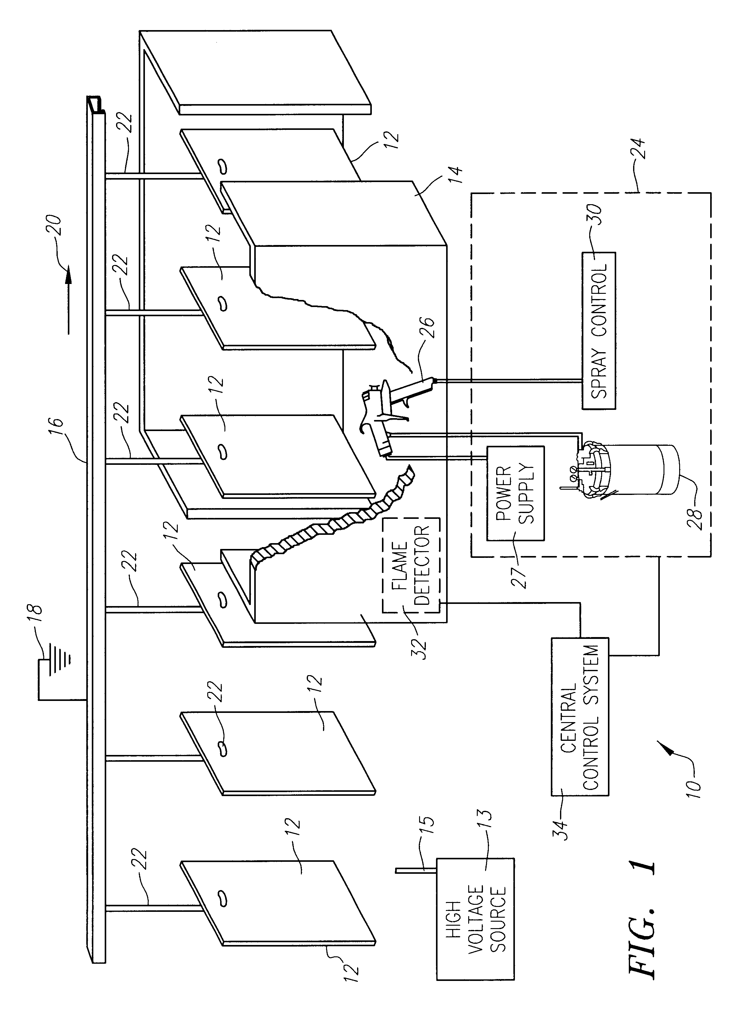
[0038]FIG. 1 illustrates an exemplary environment 10, as for example, a coating zone, such as a spray or paint booth or enclosure, in which electrostatic coating operations are routinely performed. As illustrated in FIG. 1,...


PUM


Abstract

A process and system for flame detection includes a microprocessor-controlled detector with a first sensor for sensing temporal energy in a first optical frequency range, and a second sensor for sensing temporal energy in a second optical frequency range. The temporal energy sensed in the respective first and second optical frequency ranges are transformed into respective first and second spectra of frequency components. A compensated spectrum of frequency components is generated by performing a frequency bin subtraction of the first and second spectra of frequency components. The compensated spectrum represents the energy emitted from the environment with energy emitted from false alarm sources. An average amplitude and centroid of the compensated spectrum are obtained and used to determine if a monitored phenomenon represents an unwanted fire situation. The compensated spectrum can be compared to reference compensated spectra of frequency components generated from known unwanted fire sources and known false alarm sources.

Description

CROSS REFERENCE TO RELATED APPLICATIONS[0001]This application is a continuation application of U.S. application Ser. No. 09 / 649,147, filed on Aug. 25, 2000, now U.S. Pat. No. 6,507,023 presently allowed, which claims priority to U.S. Provisional Application Ser. No. 60 / 151,190, filed on Aug. 27, 1999, now expired, and which is also a continuation-in-part of U.S. application Ser. No. 08 / 866,023, filed May 30, 1997, now U.S. Pat. No. 6,153,881, which is a national stage of PCT / US 97 / 03327, filed on Feb 28, 1997, which is a continuation-in-part of U.S. application Ser. No. 08 / 690,067 filed Jul. 31, 1996, now U.S. Pat. No. 6,046,452, which is a continuation-in-part of U.S. application Ser. No. 08 / 609,740, filed on Mar. 1, 1996, now U.S. Pat. No. 5,773,826. Each of the foregoing applications is hereby incorporated by reference as if set forth fully herein.FIELD OF THE INVENTION[0002]The field of the present invention pertains to apparatus and methods for detecting sparks, flames or fire....

Claims


Application Information

Patent Timeline
Patent Type & Authority Patents(United States)
IPC IPC(8): G08B29/00G08B29/18G08B17/12
CPCG08B17/12G08B25/002G08B29/183G08B29/24
Inventor PARHAM, OWEN D.CASTLEMAN, DAVID A.
Owner HONEYWELL INT INC
Why Eureka
Try Eureka