Rotor assembly for an electrical machine and permanent magnet motor comprising such a rotor assembly

a permanent magnet motor and rotor assembly technology, which is applied in the direction of dynamo-electric machines, magnetic circuit rotating parts, magnetic circuit shapes/forms/construction, etc., can solve the problems of loss of torque, permanent magnets producing cogging torque effects, and inefficient use of magnetic energy dissipation in this area, so as to reduce the size of the air gap, reduce the stray flux, and reduce the effect of cogging torqu

Inactive Publication Date: 2005-08-09
MINEBEAMITSUMI INC
View PDF24 Cites 21 Cited by
  • Summary
  • Abstract
  • Description
  • Claims
  • Application Information

AI Technical Summary

Benefits of technology

[0021]By changing the inclination angle α it is very easy to change the size of the pole arc along the outer periphery of the rotor and thus the density of the magnetic flux, or flux concentration, going through this pole. The main function of the angle β, separating the magnet sections, is the control of the cogging torque. It is possible to achieve a low cogging torque by suitably adjusting the angle β. However, the specific value of this angle depends on the whole construction of the magnet core. An expert will be able to find the best angle β with undue experimentation. Angle β, additionally, limits the stray flux in the zone between the magnet sections. Small values of β lead to a smaller stray flux and vice versa.
[0022]In a particularly advantageous embodiment of the invention, slots are provided in the body for receiving the magnet sections, the slots extending from the inner opening of the body towards the outer periphery of the body. In particular, the slots are closed at the outer periphery of the body so as to protect the magnets against mechanical and electromagnetic damage under operation. The provision of slots for receiving the magnets which are closed towards the air-gap side makes it possible to protect the magnets by a bridge against any possible mechanical damage. As the magnets are protected by the rotor body itself, there is no need for an additional retaining tube surrounding the motor and keeping the magnets in place. As a consequence, the size of the air-gap can be reduced. As there is no (metal) retaining tube provided around the rotor body, the size of the air-gap can be reduced, and the energy from the magnet can be transferred more efficiently to the stator so that there is less energy loss and a more effective motor can be achieved.
[0023]As a consequence, the volume of magnetic material can be reduced when compared with a surface magnet designed under equal conditions otherwise. Accordingly, with the proposed arrangement of the magnet sections in slots which are closed at the outer periphery of the body the overall efficiency of the motor can be increased.

Problems solved by technology

Accordingly, magnet energy dissipated in this area can't be used efficiently.
With the radial arrangement of the permanent magnets, as shown and described in the prior art, a problem may arise in that the regular arrangement of the permanent magnets produces a cogging torque effect which is disadvantageous in the operation of the motor.
Skewed magnetization of the rotor poles, however, creates an axial component of the magnetic force and thus a loss of torque.
Further, the problem of the cogging torque produced during operation of the electrical motor has not yet been solved satisfactorily for rotors having embedded magnets of the type described above.

Method used


Image

  • Rotor assembly for an electrical machine and permanent magnet motor comprising such a rotor assembly
  • Rotor assembly for an electrical machine and permanent magnet motor comprising such a rotor assembly
  • Rotor assembly for an electrical machine and permanent magnet motor comprising such a rotor assembly

Examples


Embodiment Construction

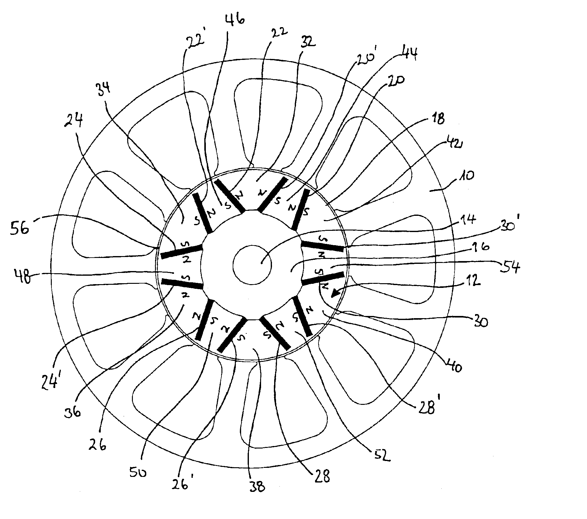
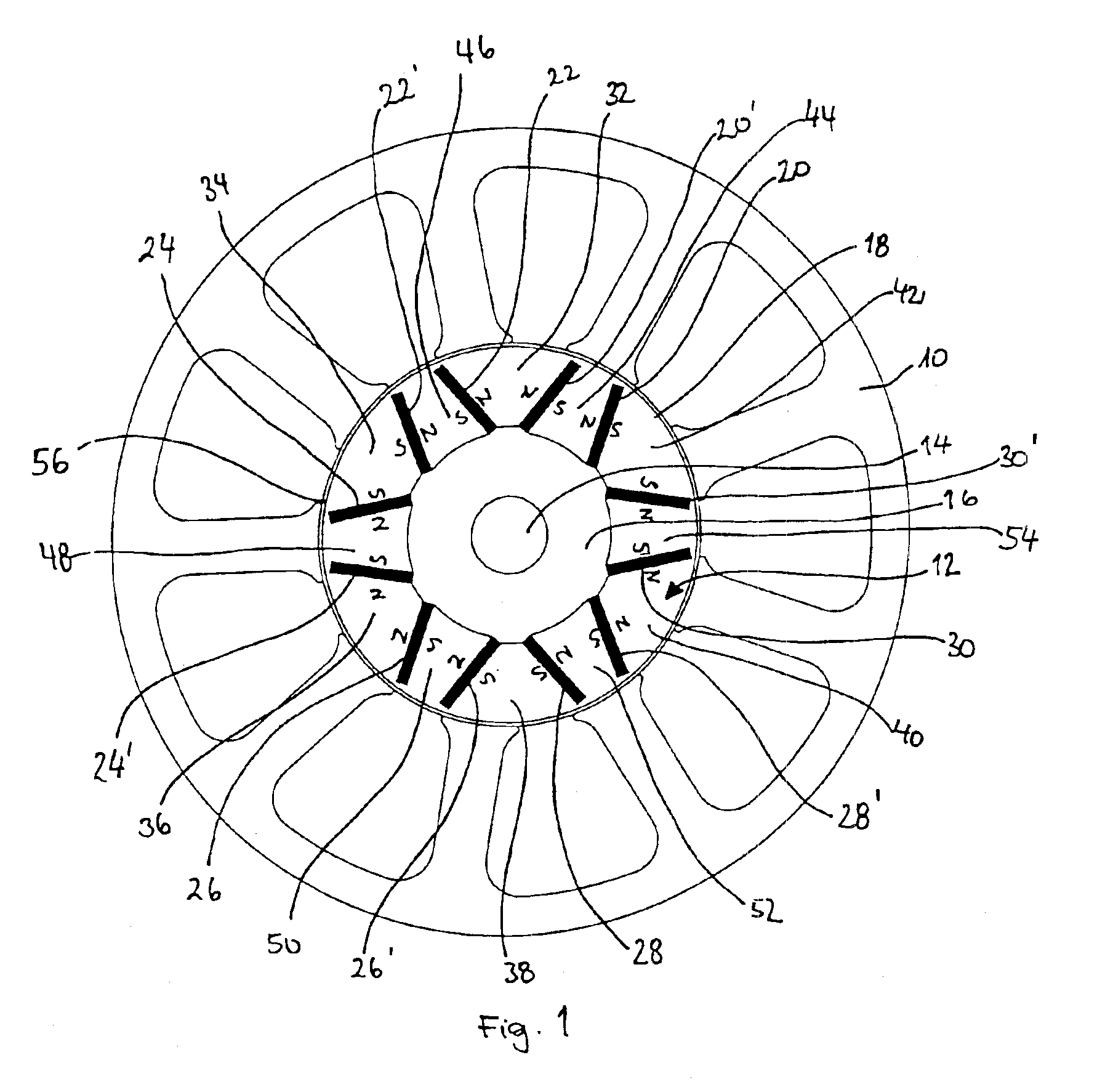
[0033]FIG. 1 schematically shows a sectional view through a brushless P.M. (Permanent Magnet) motor according to the present invention. The motor comprises a stator 10 and a rotor assembly 12 according to the present invention. The rotor assembly 12 is mounted on a shaft 14 via a hub 16. The rotor assembly 12 comprises a rotor body 18 comprising a magnetic core and a yoke and magnet sections 20, 20′; 22, 22′; 24, 24′; 26, 26′; 28, 28′; 30, 30′. Each pair of magnet sections 20, 20′; 22, 22′; 24, 24′; 26, 26′; 28, 28′; 30, 30′ forms one permanent magnet of the rotor assembly 12, with magnetic poles 32, 32, 34, 36, 38, 40, 42 formed between the magnets and neutral zones 44, 46, 48, 50, 52, 54 formed between each pair of magnet sections. The magnetisation of the core material of the rotor body 18 is indicated by N (north) and S (south) in the drawing.

[0034]Further, an air-gap 56 is provided between the stator 10 and the rotor body 12. An expert will understand that a brushless P.M. moto...


PUM


Abstract

Rotor assembly for an electrical machine, wherein a body of generally cylindrical shape having an inner opening for coaxially mounting the body on a shaft, permanent magnets embedded in said body, wherein at least one of the permanent magnets is split in at least two magnet sections which extend from about the inner opening towards the outer periphery of the body and are inclined towards a plane, which extends in a radial direction of the body.

Description

BACKGROUND OF THE INVENTION[0001]The present invention relates to a rotor assembly for an electrical machine and a P.M. (Permanent Magnet) motor comprising such a rotor assembly. In general, the invention relates to the field of brushless D.C. and P.M. synchronous motors comprising permanent magnets which can be configured to include an interior rotor surrounded by a stator (Innenläufermotor) or on outer rotor configuration (Auβenläufermotor). Electrical machines having an interior rotor include a rotor assembly which is mounted on the shaft and one or more permanent magnets as well as a stator assembly, such as a stator laminated from a number of metal sheets, comprising windings. The rotor assembly is coaxially inserted into the stator assembly. In electrical machines having outer rotors the rotor assembly surrounds the stator.[0002]FIG. 5 schematically shows the general design of an electrical machine, comprising a housing 114, in which are included the stator assembly 118, the r...

Claims


Application Information

Patent Timeline
Patent Type & Authority Patents(United States)
IPC IPC(8): H02K1/27H02K1/22H02K21/16
CPCH02K1/2766
Inventor POPOV, VLADIMIR VLADIMIROVICH
Owner MINEBEAMITSUMI INC
Why Eureka
Try Eureka