Antenna arrangement in the aperture of an electrically conductive vehicle chassis

Inactive Publication Date: 2005-08-09
DELPHI DELCO ELECTRONICS EUROPE GMBH
View PDF2 Cites 18 Cited by
  • Summary
  • Abstract
  • Description
  • Claims
  • Application Information

AI Technical Summary

Benefits of technology

[0005]It is therefore an object of this invention to avoid the disadvantage of narrow bandwidth resulting from low-loss matching by using an antenna arrangement with an aperature length L, and an aperture width B which is less than ⅓ of the length, and disposed in the conductive vehicle chassis in the meter wavelength range, so that the resonant frequency is greater than the center frequency of t

Problems solved by technology

Even for larger passenger cars, an aperture length L of greater than 90 cm is hardly available.
For the proposed antennas to conform to the impedances cust

Method used


Image

  • Antenna arrangement in the aperture of an electrically conductive vehicle chassis
  • Antenna arrangement in the aperture of an electrically conductive vehicle chassis
  • Antenna arrangement in the aperture of an electrically conductive vehicle chassis

Examples


Embodiment Construction

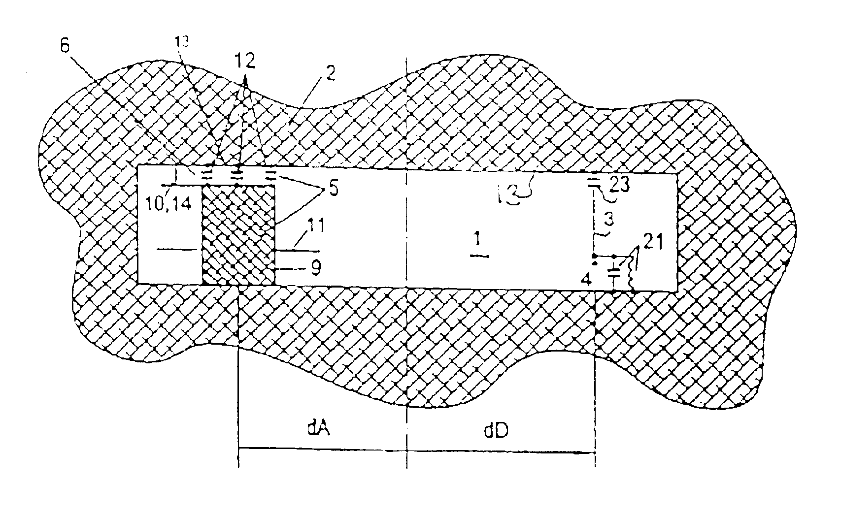
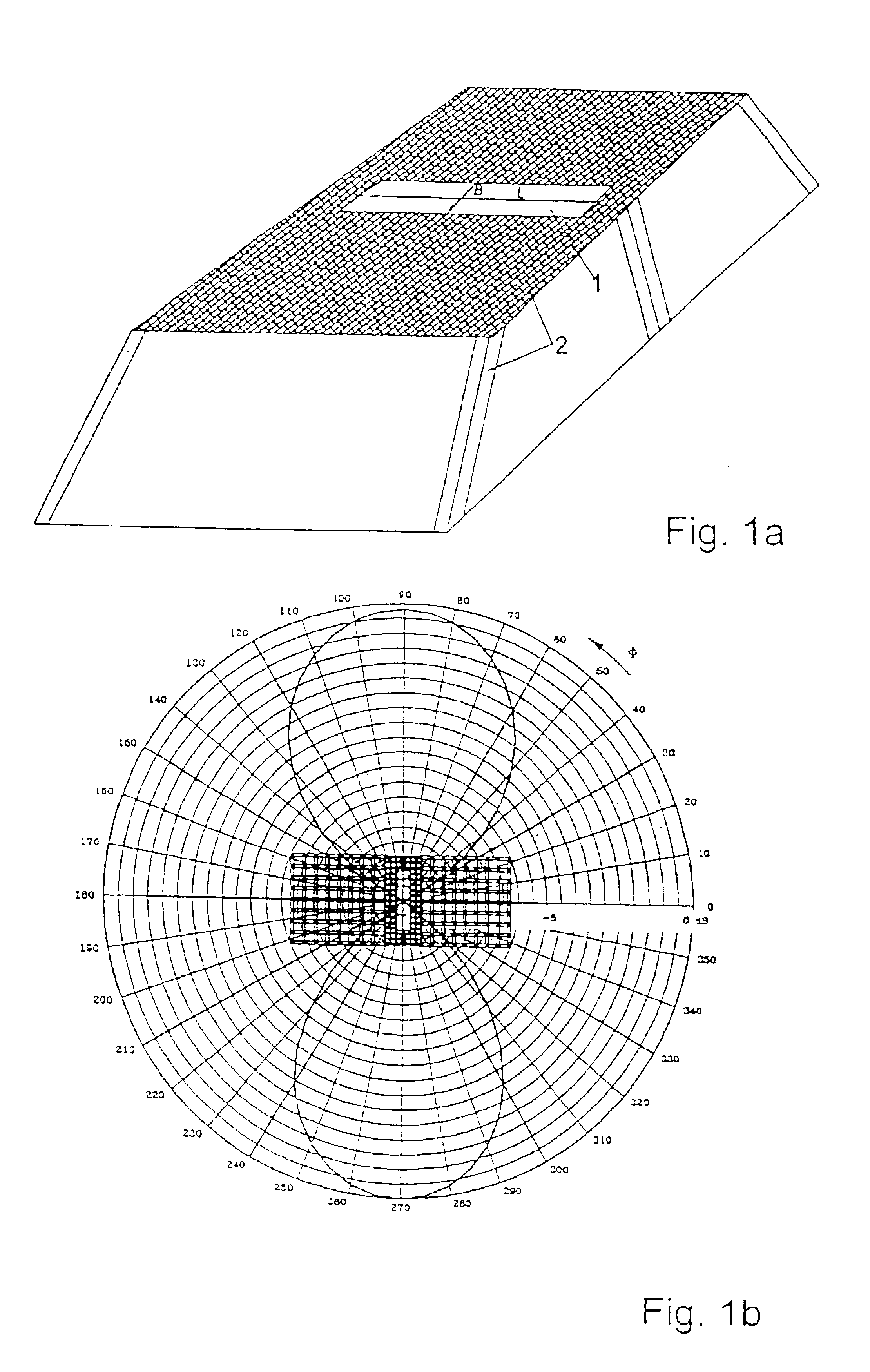
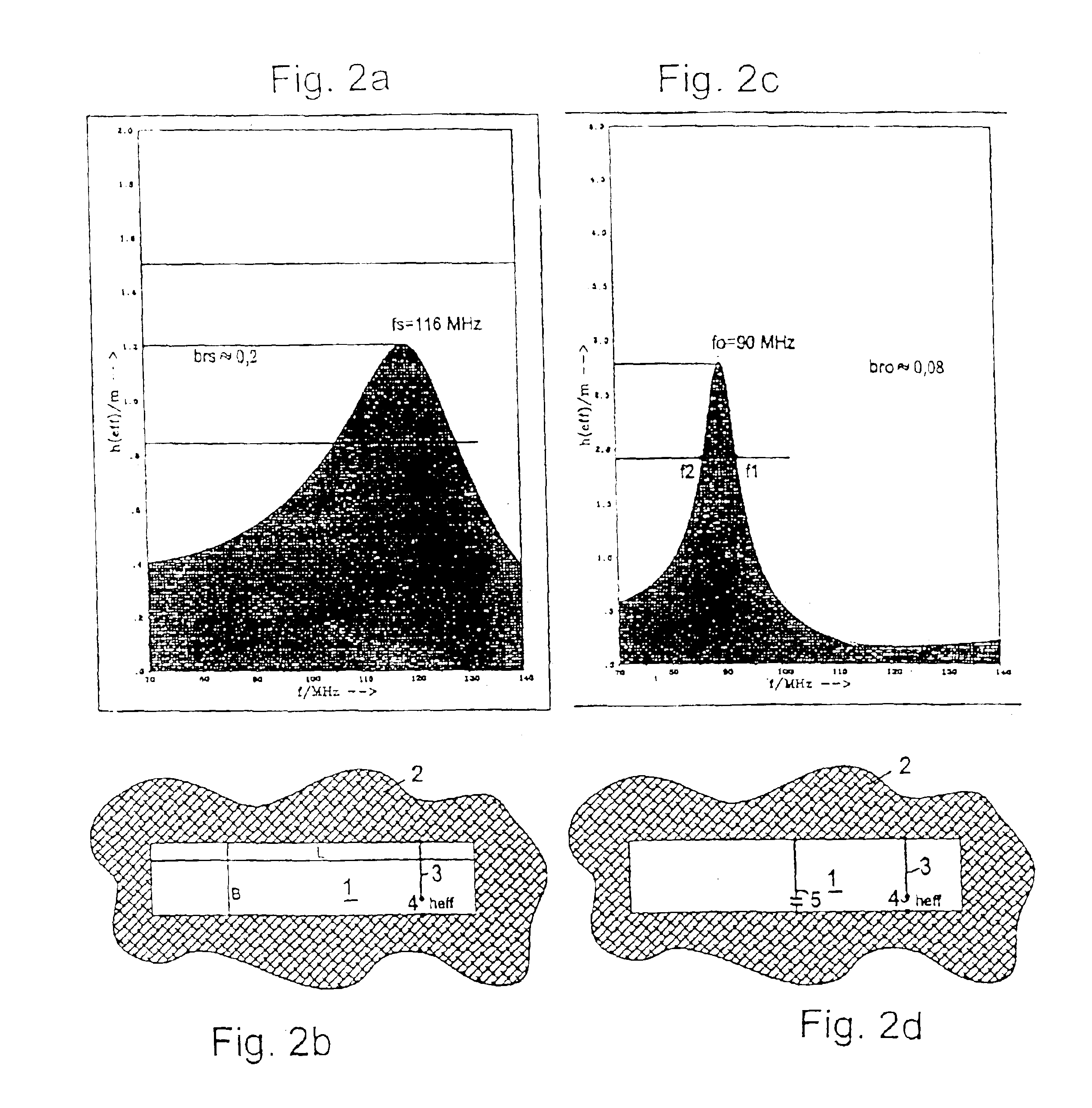
[0038]In connection with aperture lengths that are noticeably below the half-wave resonance, the radiation connected with an antenna in an aperture specified in the present invention is determined largely by the currents on the edge of the aperture. Referring to FIG. 1a, with an antenna of this type with an aperture length L and a width B, installed in the roof of a motor vehicle, a horizontal radiation, as shown in FIG. 1b, results with frequencies below the resonance of the aperture. The form of this directional diagram, which is applicable to the horizontal polarization for any type of excitation of aperture 1, is independent of the frequency to the extent that the latter does not exceed the resonance of the aperture. With respect to their own contribution to the radiation, antenna structures that are disposed in the aperture are therefore subject, at such frequencies, to the effects of the frame of the aperture. It is therefore important that the antenna structures mounted in th...


PUM


Abstract

A radio antenna arrangement disposed in the conductive surface of a vehicle consisting of a substantially rectangular aperture having aperture length L and width B, wherein said aperture length L is sufficiently small so that the self-resonant frequency of the aperture is greater than the center frequency of the operating frequency range. There is a capacitive tuning element disposed in the aperture for tuning the aperture to a resonant frequency to approximately the center frequency of the operating frequency range. The capacitive tuning element serves as capacitive connection between the edges of the aperture, and is formed as a low-inductance element, so that due to the residual inductive effect, the remaining magnetic reactive power is as small as possible relative to the magnetically generated reactive power from the magnetic fields in the aperture. An input coupling element is also disposed in the aperture for coupling the antenna connection point to the resonance like high electromagnetic fields.

Description

BACKGROUND OF THE INVENTION[0001]1. Field of the Invention[0002]This invention relates to an antenna configuration in a primarily rectangular or trapezoidal aperture of an electrically conductive vehicle chassis in the meter wavelength range, for example for UHF reception.[0003]2. The Prior Art[0004]The invention is based on an antenna system as described, for example, in German Patent 195 35 250 A1 in FIG. 4a of the roof segment for a small vehicle. The antennas described therein for frequencies up to the meter wave length region are preferably designed as thin conductive wires. Due to the limited available space in vehicle construction, primary consideration for locating the above-described segments is given to roof segments or segments in the conductive trunk cover. The aperture length L is constrained by the width of the vehicle. Its aperture width B is also constrained by other technical structural requirements, e.g. sliding roof, roll-over security, etc. This results, in parti...

Claims


Application Information

Patent Timeline
IPC IPC(8): H01Q13/10H01Q1/32
CPCH01Q1/3216H01Q1/325H01Q13/10
Inventor LINDENMEIER, HEINZHOPF, JOCHENREITER, LEOPOLD
Owner DELPHI DELCO ELECTRONICS EUROPE GMBH
Why Eureka
Try Eureka