Apparatus for measuring a measurement object

a technology for measuring objects and apparatuses, applied in measurement devices, instruments, using optical means, etc., can solve problems such as obviating the above-mentioned conduction error

Inactive Publication Date: 2005-08-09
WERTH MESSTECHN
View PDF3 Cites 25 Cited by
  • Summary
  • Abstract
  • Description
  • Claims
  • Application Information

AI Technical Summary

Benefits of technology

[0009]Taking this prior art as a departure point, the present invention is based on the object of providing an apparatus for measuring a measurement object contactlessly in which the contouring error explained above is avoided or at least significantly reduced.
[0011]In the case of this measurement apparatus, the focussing of the measurement object does not have to be continuously readjusted during a scan operation, since the evaluation unit can evaluate the measurement signals within the entire measurement window of the receiver device. As a result of this, the contouring error described above is obviated, provided that the light reflected from the measurement object is received by the receiver device within the measurement window. Only if the reflected light drifts out of the measurement window does the focussing of the measurement object have to be readjusted. Consequently, the measurement apparatus of the invention is suitable in particular for measurement objects having very planar and flat surfaces, as often occur in the semiconductor industry. With a scan accuracy remaining consistently high, the scan speed can be significantly increased since the mechanical readjustment of the focussing is completely omitted or at least minimized, which leads to significantly reduced measurement times.
[0013]For easier and / or faster further processing of the measurement data, it may be advantageous to use a CCD chip as position-sensitive receiver, which CCD chip generates digital measurement data directly.
[0015]Preferably, in addition, the transmission power of the light source can be controlled in a manner dependent on the light intensity—received by the receiver device—of the light beam reflected from the measurement object. In this way, the optical sensor can automatically react for example to different reflection properties of the measurement object and ensure a sufficiently strong reception signal at any time.
[0018]In order to increase the measurement accuracy and the application flexibility, it is furthermore advantageous if the video sensor is set up in the optical axis of the focussing device on the same beam path as the laser probe, i.e. the laser beam of the laser probe and the light from the video sensor run through the same measurement objective with the same optical axis and the midpoint of the laser spot on the measurement object is adjusted precisely in the midpoint of the video measurement region. Consequently, the laser probe and the video sensor always detect the same measurement point on the measurement object.

Problems solved by technology

As a result of this, the contouring error described above is obviated, provided that the light reflected from the measurement object is received by the receiver device within the measurement window.

Method used


Image

  • Apparatus for measuring a measurement object
  • Apparatus for measuring a measurement object
  • Apparatus for measuring a measurement object

Examples


Embodiment Construction

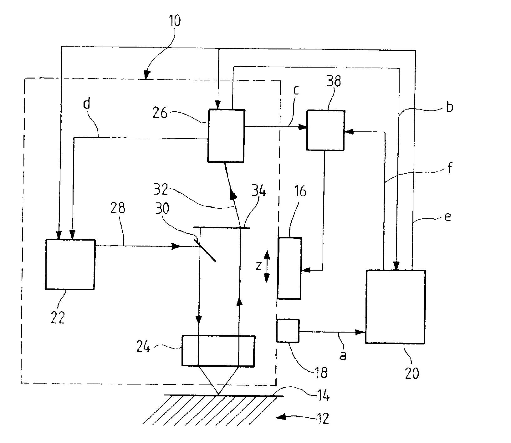
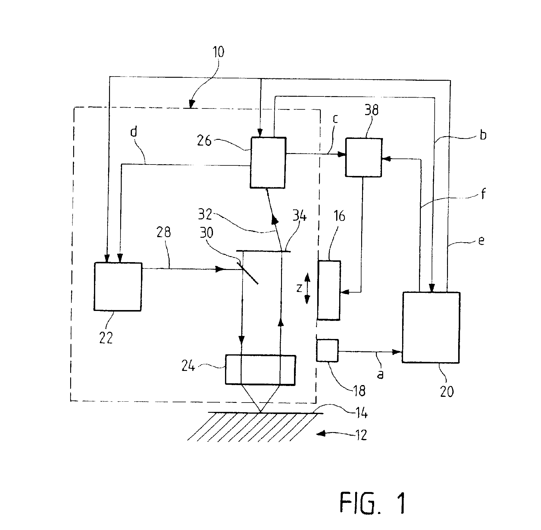
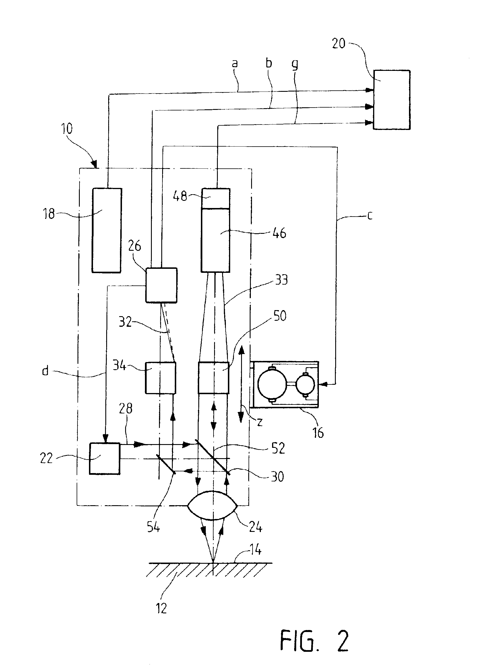
[0026]First, a measurement apparatus according to a first exemplary embodiment of the invention and the functional principle on which the invention is based will be explained with reference to FIG. 1. Further preferred exemplary embodiments of the measurement apparatus according to the invention will subsequently be described with reference to FIGS. 2 to 4. In order to provide a better understanding, identical components of the measurement apparatus are provided with the same reference symbols in all the figures.

[0027]The optical sensor 10—illustrated in FIG. 1—for measuring a measurement object 12 or the surface 14 of a measurement object 12 is preferably fitted to the measurement apparatus in such a way that it can be moved in the x-y plane, i.e. the plane perpendicular to the plane of the drawing. As a result of this, given a fixed measurement table for the measurement object 12, it is possible to achieve a relative movement between optical sensor 10 and measurement object 12 bot...


PUM


Abstract

An apparatus for contactlessly measuring a measurement object is proposed, which has an optical sensor, the optical sensor having an optical probe having a light source and a measurement objective for directing a light beam onto a measurement object and a receiver device for detecting a light beam reflected from the measurement object and generating a corresponding measurement signal; an advancing apparatus for altering the distance between the optical sensor and the measurement object in a first coordinate direction in a manner dependent on the measurement signal generated by the receiver device; and an evaluation unit for determining the coordinates of the measurement point on the measurement object. In order to avoid or at least reduce a so-called contouring error that occurs in conventional measurement apparatuses, the receiver device has a position-sensitive receiver which generates an evaluatable measurement signal within a programmable measurement window; the advancing apparatus sets the distance between the optical sensor and the measurement object in such a way that the receiver of the receiver device receives the light beam reflected from the measurement object within the measurement window; and the evaluation unit determines the coordinates of the measurement point on the measurement object from the position of the optical sensor and the measurement signal generated by the receiver device.

Description

BACKGROUND OF THE INVENTION[0001]1. Technical Field[0002]The present invention relates to an apparatus for contactlessly measuring a measurement object, more precisely the surface of a measurement object, with an optical sensor.[0003]2. Prior Art[0004]Various embodiments of such measurement apparatuses for a contactless measurement of measurement objects are already disclosed in the prior art, contactless measurements often being combined with contact-making, i.e. mechanically probing, measurements.[0005]Furthermore, such measurement apparatuses are known both for one-dimensional measurement only in one coordinate axis (z axis) and for multicoordinate measurement in the form of 2D or 3D measurement apparatuses in which, in addition to the z coordinate of the measurement point on the measurement object, the x and / or y coordinate thereof can also be detected.[0006]Such a multicoordinate measurement apparatus is disclosed for example in U.S. Pat. No. 4,908,951 by W. H. Gurny. In the ca...

Claims


Application Information

Patent Timeline
Patent Type & Authority Patents(United States)
IPC IPC(8): G01B11/02G01B11/00G01B11/24
CPCG01B11/005G01B11/026G01B11/24
Inventor GURNY, WERNER H.
Owner WERTH MESSTECHN
Why Eureka
Try Eureka