
Rach receiving apparatus

a receiving apparatus and receiver technology, applied in the field of correlation circuits for spread spectrum communication, can solve the problems of large hardware scale, and increasing the number of gates, so as to reduce the power consumption, the circuit scale can be further reduced, and the power consumption can be reduced.

Inactive Publication Date: 2005-08-09
KOKUSA ELECTRIC CO LTD
View PDF2 Cites 2 Cited by
  • Summary
  • Abstract
  • Description
  • Claims
  • Application Information

AI Technical Summary

Benefits of technology

[0031]According to the present invention, it is an object to provide an RACH receiving apparatus in which components can be constructed in a small scale.
[0032]According to the present invention, there are provided an RACH receiving apparatus for demodulating a reception signal spread-spectrum by long codes, phase rotation information, and signatures, the apparatus comprising: a first multiplying unit for multiplying the reception signal by first despreading codes operated by the long codes and phase rotation information; a first adding unit for adding a plurality of multiplication results outputted from the first multiplying unit at specific intervals; a second multiplying unit for multiplying a plurality of addition results outputted from the first adding unit by second despreading codes of the signatures; and a second adding unit for adding multiplication results outputted from the second multiplying unit to obtain correlation outputs. A demodulation processing is performed so as to be divided into two stages of a first demodulation processing with the first despreading code and a second demodulation processing with the second despreading code, thereby reducing the total number of adders. Consequently, the circuit scale can be reduced and the power consumption can be reduced.
[0033]According to the present invention, the above RACH receiving apparatus includes a complex operating unit for performing a complex operation to correlation outputs generated from the second adding unit. The apparatus can modulate a complex-modulated reception signal and obtain correct correlation outputs.

Problems solved by technology

Accordingly, the scale of the hardware is large.
On the other hand, the adder has to perform the addition of long bits (6 bits to tens of bits), so that the hardware scale becomes large.
As mentioned above, in the conventional MF, to detect the Preamble part of the RACH in the base station, the complex MF is needed as much as the number of signatures, so that there are such problems that the number of gates is increased, the circuit scale is increased, and the cost of LSI to construct the MF is raised.

Method used


Image

  • Rach receiving apparatus
  • Rach receiving apparatus
  • Rach receiving apparatus

Examples


embodiment 1

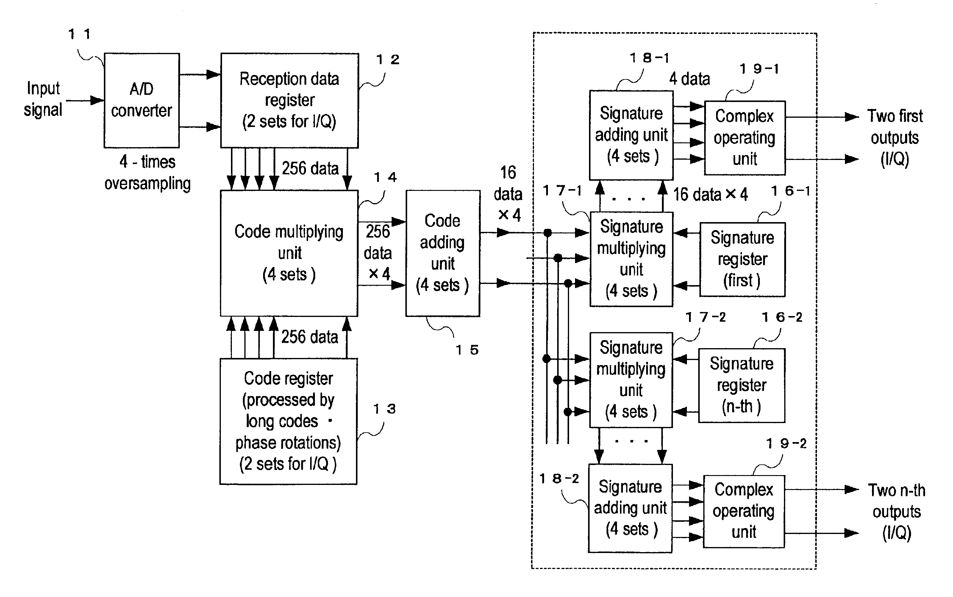
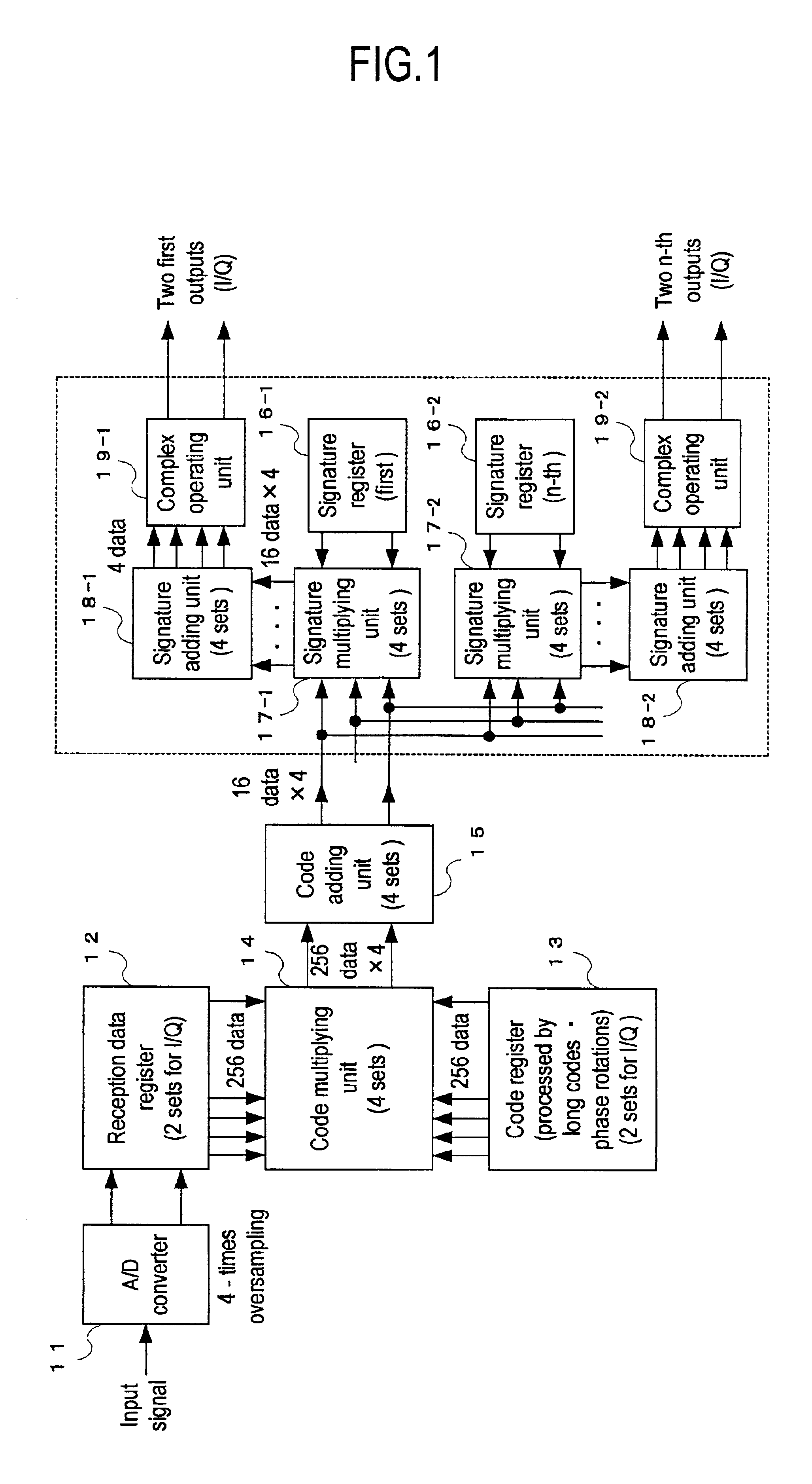
[0062]The MF according to the present invention comprises: an A / D converter 11; a reception data register 12; a code register 13; a code multiplying unit 14; a code adding unit 15; signature registers 16-1 and 16-2; signature multiplying units 17-1 and 17-2; signature adding units 18-1 and 18-2; and complex operating units 19-1 and 19-2.

[0063]The A / D converter 11 converts an analog signal received by an antenna (not shown) of the RACH receiving apparatus into digital reception signals at a speed that is four times as high as a transmission rate of the analog signal. The transmission speed of the analog signal is equal to 4 Mcps. The A / D converter converts the analog signal of one bit including an in-phase component (hereinbelow, referred to as an I component) and a quadrature component (hereinbelow, referred to as a Q component) into digital reception signals of multi-bits at 16 Mbps that is four times as high as the above speed, respectively.

[0064]The reception data register 12 has...

embodiment 2

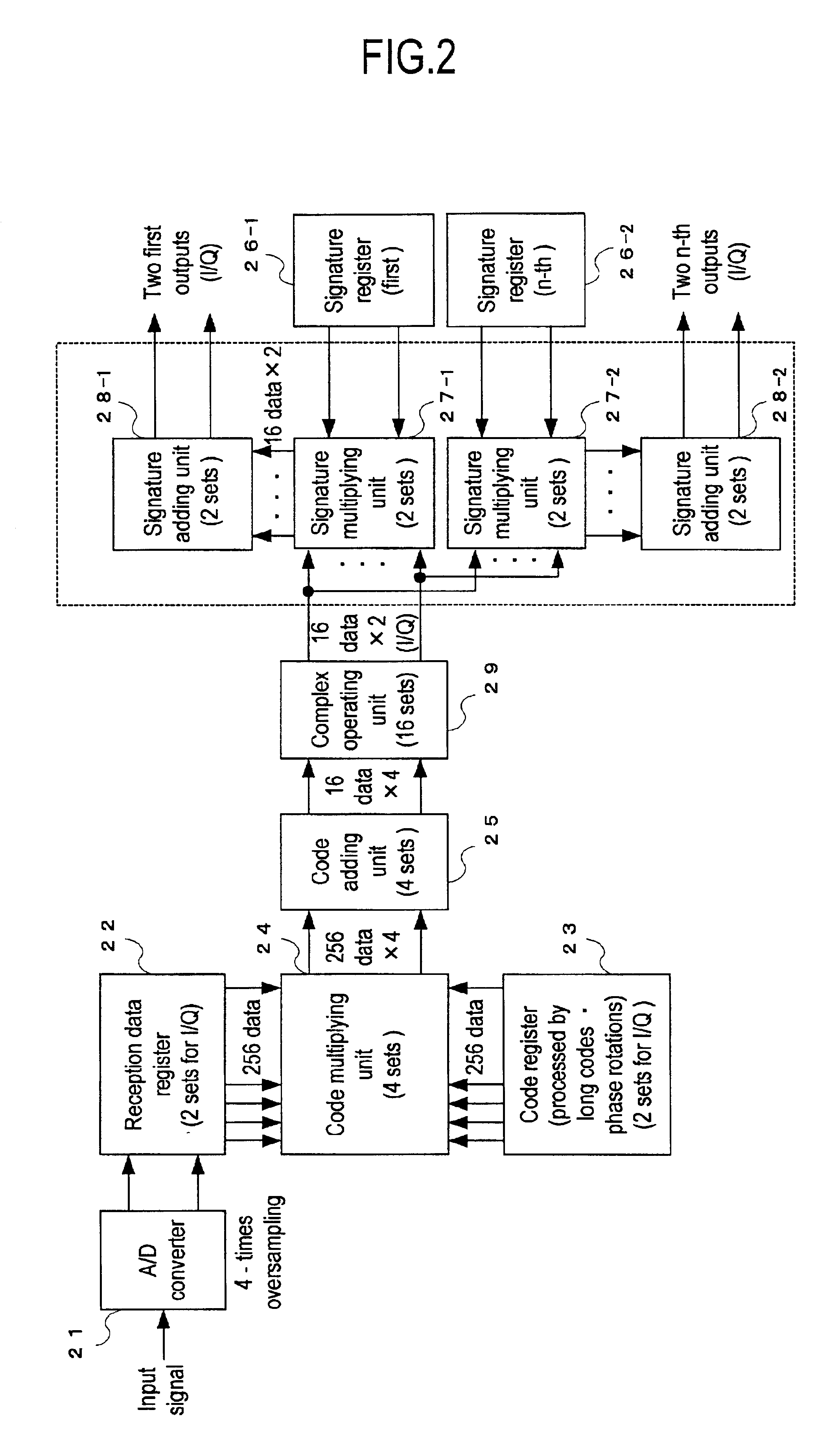
[0124]The respective units constituting the MF according to the above-mentioned embodiment 2 of the present invention operate at a speed of 16 MHz.

[0125]In the MF according to the embodiment 2 of the present invention, it is necessary to provide the signature register 26, signature multiplying unit 29, and signature adding unit 28 as much as the number of kinds of signature codes used during the modulation. The constitutions and operations of the other units are the same as those of the corresponding units in the MF of FIG. 1.

[0126]As for the number of adders used in the MF according to the embodiment 2 of the present invention, the register code adding unit 25 has (15×16×4=) 960 adders, complex operating unit 29 has two adders, and each signature adding unit 28 has (15×2=) 30 adders. When the number of kinds of signature codes used during the modulation is set to n, the total number of adders used in the MF of the embodiment 2 of the present invention is expressed by (962+30×n). It...

embodiment 3

[0142]Also in the MF according to the present invention, it is necessary to provide the signature register 36, signature multiplying unit 37, and signature adding unit 38 as much as the kinds of the signature codes used during the modulation.

[0143]In the MF of FIG. 3, since the processing speed is doubled in the unit for performing the demodulation processing with the halfway demodulated sign codes, the power consumption of the unit whose processing speed is raised is twice as high as that of the MF of FIG. 2. On the other hand, when the circuit scale is compared with that of the MF in FIG. 2, 4 multiplier groups can be reduced in half to 2 groups in the code multiplying unit 34, the number of multipliers can be reduced by (256×2=) 512, and the number of adders can be reduced by (15×16×2=) 480 in the code adding unit 35. The total number of adders used in the MF of FIG. 3 is expressed as (480+30×n).

[0144]According to the embodiment 3 of the present invention, the MF has such a const...


PUM


Abstract

The present invention provides an RACH receiving apparatus in which the components can be constructed in a small scale.The RACH receiving apparatus performs a demodulation processing so as to divide it into two stages of a first demodulation processing for multiplying reception data of complex-modulated RACH by sign codes subjected to an arithmetic processing with long codes and phase rotations in a code register multiplying unit, and a second demodulation processing for adding multiplication results every chips and multiplying addition results by signature codes in a signature multiplying unit.

Description

BACKGROUND OF THE INVENTION[0001](i) Field of the Invention[0002]The present invention relates to a correlation circuit for spread spectrum communication used on a receiver side of a spread spectrum communication system in mobile communication or wireless LAN and, more particularly, to an RACH receiving apparatus for detecting an RACH with a simple and small construction.[0003](ii) Description of the Related Art[0004]Generally, in a spread spectrum (SS) communication system used in mobile communication or wireless LAN (Local Area Network), on a transmission side, transmission data is subjected to a narrow band modulation (primary modulation) and further subjected to a spreading modulation (secondary modulation), namely, data is subjected to a two-stage modulation and then transmitted.[0005]On a reception side, reception data is despread to be returned in the primary modulated state and a normal detecting circuit reconstructs a baseband signal.[0006]According to a modulation system f...

Claims


Application Information

Patent Timeline
Patent Type & Authority Patents(United States)
IPC IPC(8): H04L27/26H04K1/00H04B1/69H04B1/707H04L27/38H04L27/30H04B1/16H04B15/00H04BH04B1/7093
CPCH04B1/7093H04B1/70712
Inventor IMAIZUMI, ICHIROWATANABE, JUN
Owner KOKUSA ELECTRIC CO LTD
Learn More