Electronic compass system

a compass and electronic technology, applied in the field of electronic compass, can solve the problems of unnecessary warranty claim, process time-consuming, and inability of the processing circuit to use a simple heading angle calculation to determine the appropriate heading

Inactive Publication Date: 2005-08-09
GENTEX CORP
View PDF56 Cites 187 Cited by
  • Summary
  • Abstract
  • Description
  • Claims
  • Application Information

AI Technical Summary

Benefits of technology

[0028]According to another embodiment of the present invention, an electronic compass for a vehicle comprises: a magnetic sensor circuit for sensing at least two perpendicular components of the Earth's magnetic field vector and for generating output signals representative of the sensed components; and a processing circuit coupled to the magnetic sensor circuit for receiving the output signals, selecting a first approximating geometric pattern based on a first set of reference data points derived from the sensed components, computing a heading of the vehicle as a function of at least two of the sensed components while referencing the first approximating geometric pattern, generating a heading signal representing the computed heading, selecting a second approximating geometric pattern based on reference data points received after the first approximating geometric pattern is selected, utilizing the second approximating geometric pattern if the second approximating geometric pattern is significantly different from the first approximating geometric pattern, and reselecting the first approximating geometric pattern if the subsequently obtained reference data points better fit the first approximating geometric pattern.

Problems solved by technology

In practice, however, the plot of the outputs of the X and Y sensors on an X and Y coordinate plane often does not form a perfect circle, nor is the center of such a circle coincident with the origin of the coordinate plane.
When the actual plot is not a perfect circle and has a center point offset from the origin, the processing circuit cannot use a simple heading angle calculation to determine the appropriate heading.
One problem with the automatic calibration routine disclosed in the above-noted '305 patent is that it generally requires that the vehicle travel in numerous 360° loops to attain sufficient data for the system to have confidence that the calibration is accurate.
This poses a problem to vehicle manufacturers who must then drive each vehicle through several loops before loading the vehicle on a vehicle carrier for delivery to a dealer.
Unfortunately, there often is not sufficient space at the assembly plant for each vehicle to be driven in such loops and, even if there is space, the process takes precious time.
If the vehicles are delivered to the dealership without having been driven through sufficient loops, a customer may purchase the vehicle or otherwise test drive the vehicle with an uncalibrated compass.
In this event, the customer might erroneously be lead to believe that the compass is malfunctioning and thus make an unnecessary warranty claim with respect to the compass.
Although each of the above-noted patents discloses a calibration routine that more quickly calibrates the compass, some of the techniques disclosed are either overactive in that they recalibrate too frequently and thus are prone to calibration errors due to temporary magnetic field disturbances, or they do not respond quickly enough to changes in magnetic field variances that are more permanent in nature.
Furthermore, none of the above-noted patents disclose calibration routines that take into account the pitch of the vehicle or the strength of the vertical component of the Earth's magnetic field vector.
Accordingly, if any of the above-noted compasses are mounted such that its sensors are provided in a movable structure relative to the vehicle, such as the housing of a rearview mirror assembly, these systems would be incapable of providing a quick and accurate response to movement of the housing.
This compass system, however, does not utilize the Z-axis sensor for determining the heading or identifying the center of a circle used for calibration.

Method used


Image

  • Electronic compass system
  • Electronic compass system
  • Electronic compass system

Examples


first embodiment

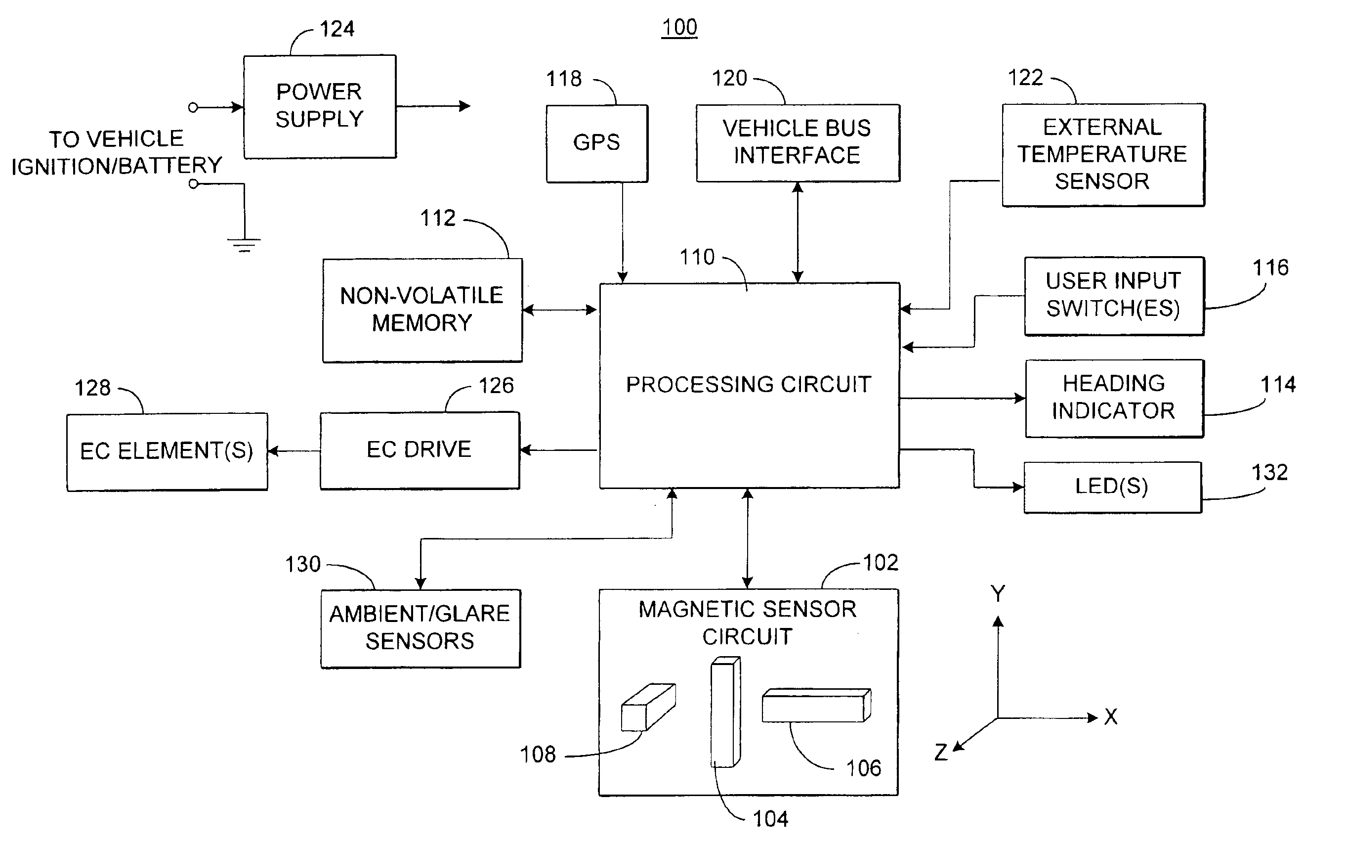
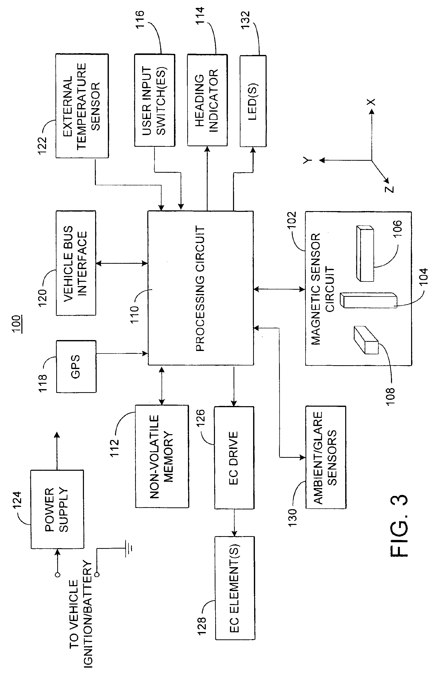
[0073]Having described the hardware for the electronic compass system, a general overview is provided below of the inventive process to be executed by processing circuit 10. Following the general overview, a detailed description of a first embodiment illustrating one implementation of some of the inventive concepts is provided with reference to FIGS. 11-21.

[0074]As noted above, in the preferred embodiments, the magnetic sensor circuit 102 includes a Z-axis sensing element 108 that is disposed substantially vertically to sense magnetic field components perpendicular to the components sensed by the X and Y axis sensors 104 and 106. Accordingly, the inventive process preferably maps the data in a three-dimensional coordinate system. Ideally, the mapped data would then correspond to a sphere rather than a circle in a single fixed plane.

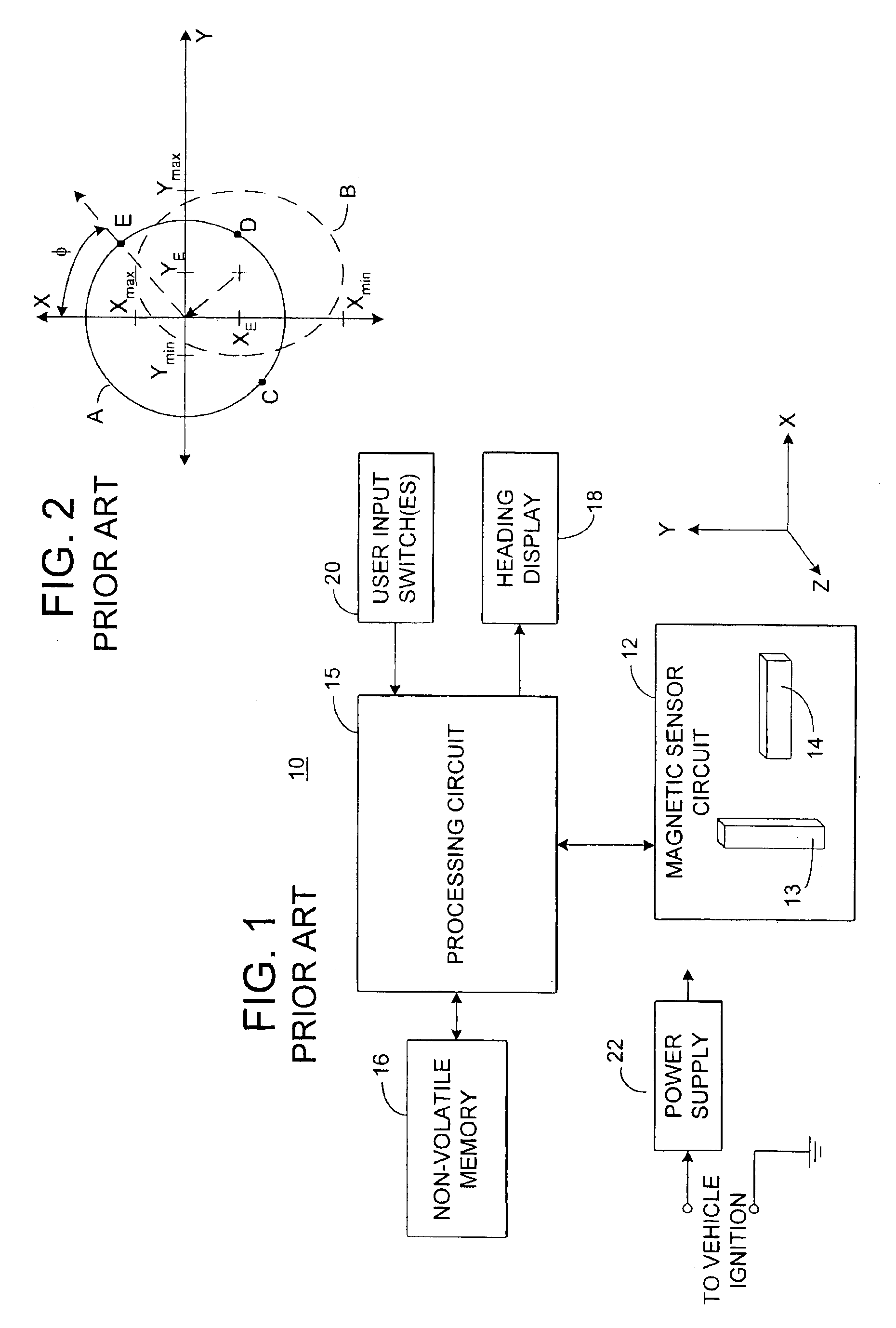
[0075]To better illustrate the principles of the present invention, reference is now made to FIG. 8, which shows the coordinate system of the magnetic se...

second embodiment

[0156]The main process flow diagram for the specific example of the second embodiment is shown in FIG. 22A. The main process 500 begins with step 502, in which the hardware is initialized. This includes initialization of I / O, memory, the magnetometer, and the display. Then in step 504, processing circuit 110 of compass circuit 100 (FIG. 3) determines whether the data stored in the nonvolatile memory (NVM) 112 is valid. If not (as would be the case upon initial startup in a new vehicle), the process flows to the decalibrate subroutine 506, which is described in detail below with respect to FIG. 22B. Otherwise, if there is valid data in NVM 112, processing circuit 110 determines whether there are enough reference points accumulated and stored for a good calibration solution (e.g., four or more reference points). If not, the decalibrate subroutine 506 is executed. Otherwise, the process proceeds to step 510 in which event driven and background tasks are started. When the process return...


PUM


Abstract

An electronic compass system includes a magnetic sensor circuit having at least two sensing elements for sensing perpendicular components of the Earth's magnetic field vector. A processing circuit is coupled to the sensor circuit to filter, process, and compute a heading. The processing circuit further selects an approximating geometric pattern, such as a sphere, ellipsoid, ellipse, or circle, determines an error metric of the data points relative to the approximating pattern, adjusts the pattern to minimize the error, thereby obtaining a best fit pattern. The best fit pattern is then used to calculate the heading for each successive sensor reading provided that the noise level is not noisy and until a new best fit pattern is identified. The electronic compass system is particularly well suited for implementation in a vehicle rearview mirror assembly.

Description

CROSS-REFERENCE TO RELATED APPLICATION[0001]This application is a continuation of U.S. patent application Ser. No. 10 / 210,910, entitled “ELECTRONIC COMPASS SYSTEM,” filed on Aug. 2, 2002, by Harold Ockerse et al., which claims priority under 35 U.S.C. §119(e) on U.S. Provisional Patent Application No. 60 / 360,723, entitled “ELECTRONIC COMPASS SYSTEM,” filed on Mar. 1, 2002, by Harold Ockerse et al., the entire disclosures of which are incorporated herein by reference.BACKGROUND OF THE INVENTION[0002]The present invention generally pertains to an electronic compass for a vehicle, and more particularly pertains to electronic compasses having improved data filtering, and / or heading determination.[0003]Electronic compasses have become increasingly popular as an accessory in automobiles. The general construction of a typical electronic compass circuit 10 is shown in FIG. 1. Specifically, a typical electronic compass circuit includes a magnetic sensor circuit 12, which includes a Y-axis se...

Claims


Application Information

Patent Timeline
Patent Type & Authority Patents(United States)
IPC IPC(8): G01C17/30G01C17/38G01C17/00
CPCG01C17/30G01C17/38G01C17/32
Inventor OCKERSE, HAROLD C.BECHTEL, JON H.BUGNO, MARK D.
Owner GENTEX CORP
Why Eureka
Try Eureka