Method of connecting partition panels

a technology of partition panels and connecting parts, applied in the field of partition arrangements, can solve the problems of limiting the number and size of different office arrangements that can be constructed, and limiting the speed with which changes occur

Inactive Publication Date: 2005-08-16
STEELCASE INC
View PDF161 Cites 50 Cited by
  • Summary
  • Abstract
  • Description
  • Claims
  • Application Information

AI Technical Summary

Benefits of technology

[0008]Yet another aspect of the present invention includes a method of connecting partition panels that comprise steps of providing a first partition panel including a partition frame having upper and lower horizontal frame members, at least one of which includes a horizontal row of horizontally spaced and aligned discrete site locators that include at least one discrete site locator positioned between vertical side edges of the partition frame. The discrete site locators are configured and adapted to locate an off-module-located second partition panel along the partition frame at any one of a number of known locations characteristically without the need to measure to accurately locate the second partition panel. The method includes steps of accurately locating the off-module-located second partition panel on the first partition panel relative to a selected one of the discrete site locators.
[0009]Yet another method of connecting partition panels comprises steps of providing a first partition panel including a partition frame having upper and lower horizontal frame members, at least one of which includes a horizontal row of horizontally spaced and aligned discrete site locators, including at least one discrete site locator positioned between vertical side edges of the partition frame. The discrete site locators are configured and adapted to locate an off-module-located furniture unit along the partition frame at any one of a number of known locations. The method includes accurately locating a furniture unit on the first partition panel relative to at least one of the discrete site locators.

Problems solved by technology

However, often the existing partition systems are limited in their ability to be reconfigured, thus limiting the number and size of different office arrangements that can be constructed, and limiting the speed with which changes can be made.

Method used


Image

  • Method of connecting partition panels
  • Method of connecting partition panels
  • Method of connecting partition panels

Examples


Embodiment Construction

[0094]For purposes of description herein, the terms “upper,”“lower,”“right,”“left,”“rear,”“front,”“vertical,”“horizontal,” and derivatives thereof shall relate to the invention as oriented in FIGS. 1 and 2. However, it is to be understood that the invention may assume various alternative orientations and step sequences, except where expressly specified to the contrary. It is also to be understood that the specific devices and processes illustrated in the attached drawings and described in the following specifications are simply exemplary embodiments of the inventive concepts defined in the appended claims. Hence, specific dimensions and other physical characteristics relating to the embodiments disclosed herein are not to be considered as limiting, unless the claims expressly state otherwise.

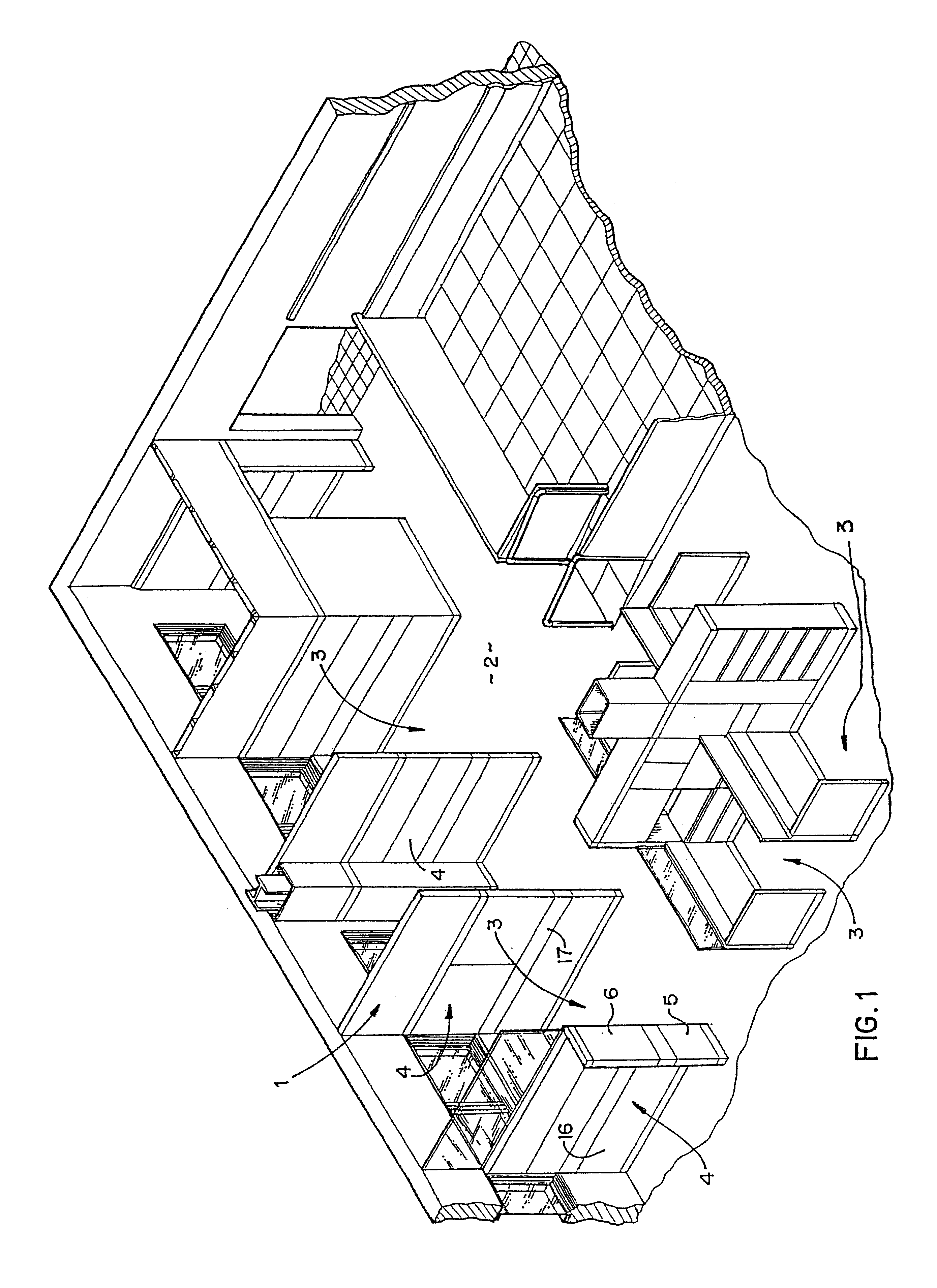
[0095]The reference numeral 1 (FIG. 1), generally designates a freestanding portable partition system that is designed for use in conjunction with open office spaces 2, and other similar environ...


PUM


Abstract

A freestanding portable partition panel system is provided for open office spaces and the like. Each panel includes a partition frame having vertical upright frame members positioned adjacent opposite side edges thereof, and multiple horizontal frame members attached to the upright frame members in a vertically spaced-apart relationship to rigidly interconnect the same. One or more horizontal rows of discrete slots are defined in each of the horizontal frame members. Cover panels are mounted on the partition frames that permit access to the slots, and off-module connectors with hooks are provided for engaging the slots for interconnecting furniture units in off-module positions. For example, the hooks of the connectors are engaged with selected slots to hold a furniture unit, such as a partition panel, perpendicular to a second partition panel in an off-module position on its face.

Description

CROSS-REFERENCE TO RELATED APPLICATIONS[0001]The present application is a divisional of coassigned U.S. application Ser. No. 09 / 585,877, filed Jun. 1, 2000 now U.S. Pat. No. 6,397,532, entitled PARTITION FRAME CONSTRUCTION HAVING WIREWAYS AND OFF-MODULE CONNECTION, which is a continuation of coassigned application Ser. No. 09 / 335,026, filed Jun. 17, 1999, now U.S. Pat. No. 6,134,852, issued Oct. 24, 2000, entitled PARTITION FRAME CONSTRUCTION HAVING WIREWAYS AND OFF-MODULE CONNECTION, and also is a continuation of coassigned application Ser. No. 09 / 335,373, filed Jun. 17, 1999, now U.S. Pat. No. 6,167,676, issued Jan. 2, 2001, entitled METHOD OF CONNECTING PARTITIONS, both of which are a continuation of co-assigned application Ser. No. 09 / 067,731, filed Apr. 28, 1998, now U.S. Pat. No. 6,044,612, issued Apr. 4, 2000, entitled CONNECTION SYSTEM FOR PARTITIONS, which is a continuation of application Ser. No. 08 / 579,614, filed Dec. 26, 1995, now U.S. Pat. No. 5,746,035, issued May 5, 1...

Claims


Application Information

Patent Timeline
Patent Type & Authority Patents(United States)
IPC IPC(8): A47B57/00A47B57/42A47B96/06A47B96/00A47B96/04E04B2/74E06B3/50E06B3/32E04F11/00E04C2/30
CPCA47B57/425A47B96/06E04B2/7424E04B2/7425E04B2/7433E04B2/7448E04B2/7453E04B2/7455E04F11/00E06B3/5045A47B96/04Y10S52/13E04B2002/7461E04B2002/7462E04B2002/7466E04B2002/747E04B2002/7483E04B2002/7487E04B2002/749Y10T403/557Y10T403/591
Inventor SHIPMAN, DAVID A.SHAW, BENJAMIN G.SEIBER, CHARLES A.MINAMI, DON S.MCCLANAHAN, DAVID D.LUCHETTI, ROBERT J.LADA, CHRISTOPHER O.HOBSON, PHILLIP M.ELDON, III, JAMES B.DRAUDT, GREGG R.
Owner STEELCASE INC
Why Eureka
Try Eureka