

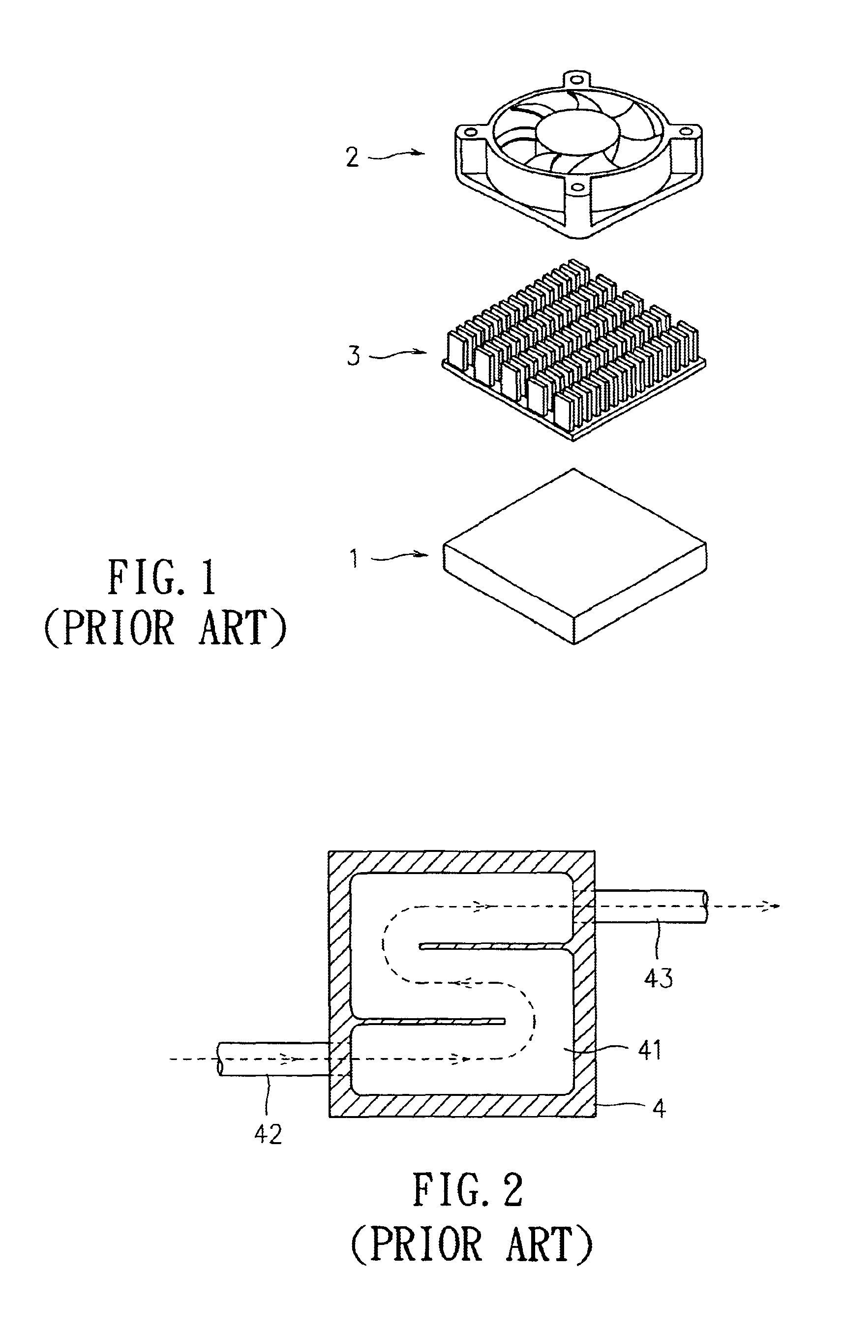
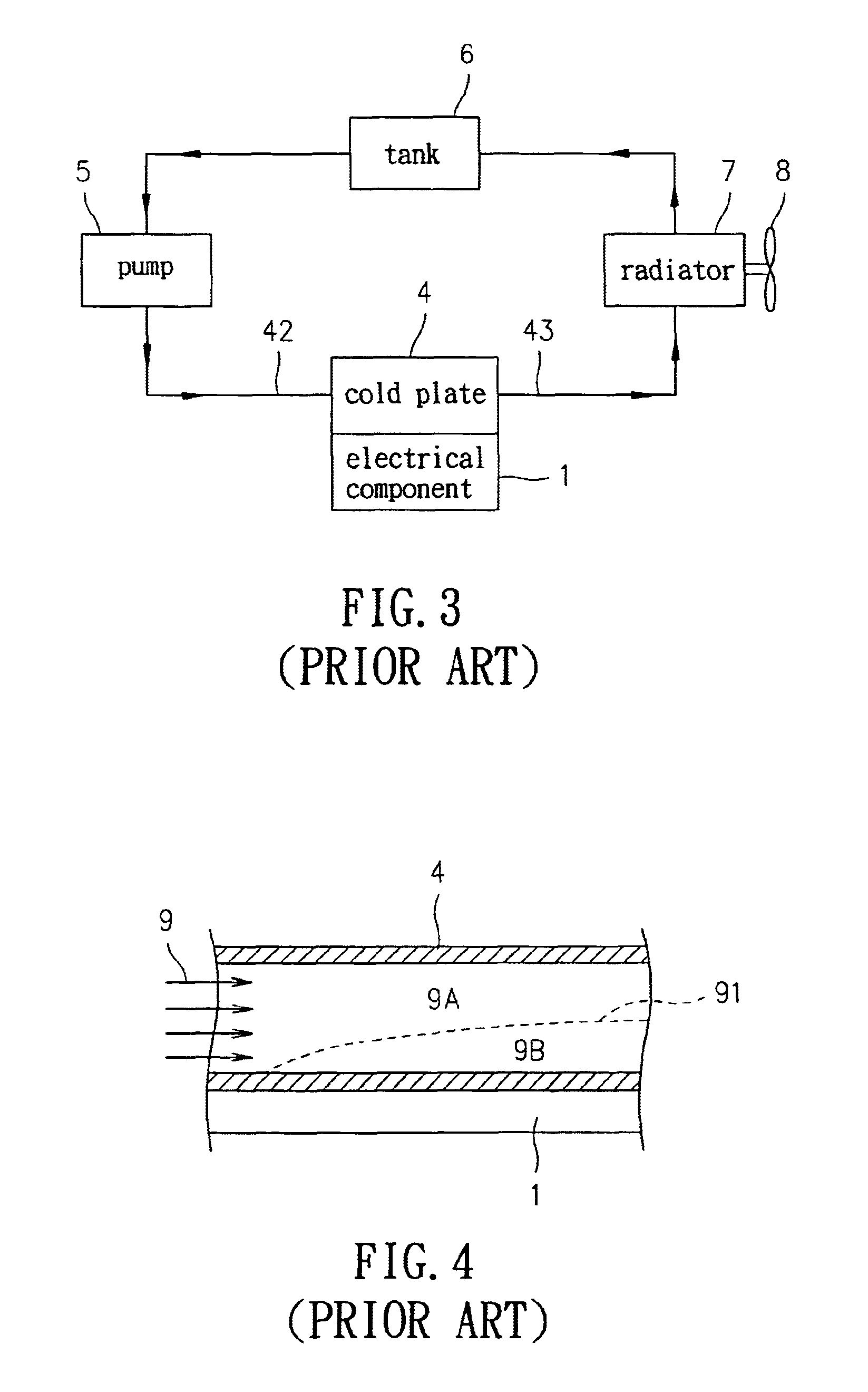
Cold plate with vortex generator
a generator and cold plate technology, applied in the direction of basic electric elements, lighting and heating apparatus, semiconductor devices, etc., can solve the problems of extreme damage to both the electrical component and the system using the component, and the heat load becomes a very important issue, so as to improve the heat transfer, improve the heat transfer effect, and improve the effect of liquid mixtur
- Summary
- Abstract
- Description
- Claims
- Application Information
AI Technical Summary
Benefits of technology
Problems solved by technology
Method used
Image

Examples
Embodiment Construction
[0024]Referring to FIG. 5 and FIG. 6, which are a partial exploded 3-D view of a preferred embodiment of the present invention and an assembled 3-D view of the preferred embodiment of the present invention, wherein a cold plate 10 comprises a base 11 and a plate 12.
[0025]The base 11 has a plurality of parallel partition plates 111 therein. The partition plates 111 form a groove 112 in circuitous shape on a bottom of the base 11. A surface of the base 11 toward the plate 12 is set an O-ring 113 made of rubber or the like.
[0026]The plate 12 has an inlet 121 and an outlet 122 for coolant. The inlet 121 and the outlet 122 are installed respectively and correspondingly to two ends of the groove 112 of the base 11. The inlet 121 is connected to an input tube 15 externally for inputting the coolant, and the outlet 122 is connected to an output tube 16 externally for outputting the coolant.
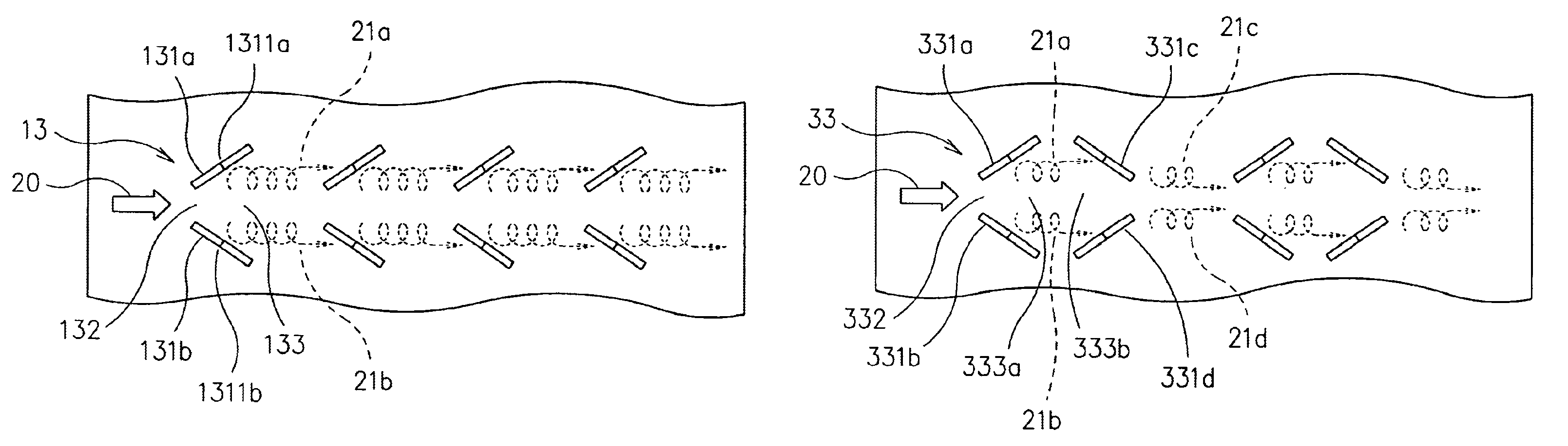
[0027]At least one vortex generator 13 is mounted on a surface of the plate 12 toward the groove 112 o...
PUM
 Abstract
Description
Claims
Application Information