Reconstruction of virtual raster

a virtual raster and reconstruction technology, applied in the field of coding pattern identification, can solve the problems of uneven signal level and/or sharpness, noise, geometric distortion, etc., and achieve the effect of efficient computation

Inactive Publication Date: 2005-08-16
ANOTO AB
View PDF24 Cites 56 Cited by
  • Summary
  • Abstract
  • Description
  • Claims
  • Application Information

AI Technical Summary

Benefits of technology

[0025]According to an embodiment for processing a sequence of digital images, a current digital image is first corrected for rotation in the image plane via a first transformation matrix, after which the above-mentioned homogeneous transformation matrix is computed based on the rotation-corrected image. Before

Problems solved by technology

Generally, and in particular when the coding pattern is detected with a hand-held device such as a digital pen or scanner, the resulting image will contain, in addition to objects which correspond to the marks, also interference in the form of noise, geometric distortion, unevenness in signal level and/or sharpness, etc.
It is therefore generally a problem, before the decoding of the coding pattern, to be able to identify the symbols

Method used


Image

  • Reconstruction of virtual raster
  • Reconstruction of virtual raster
  • Reconstruction of virtual raster

Examples


first embodiment

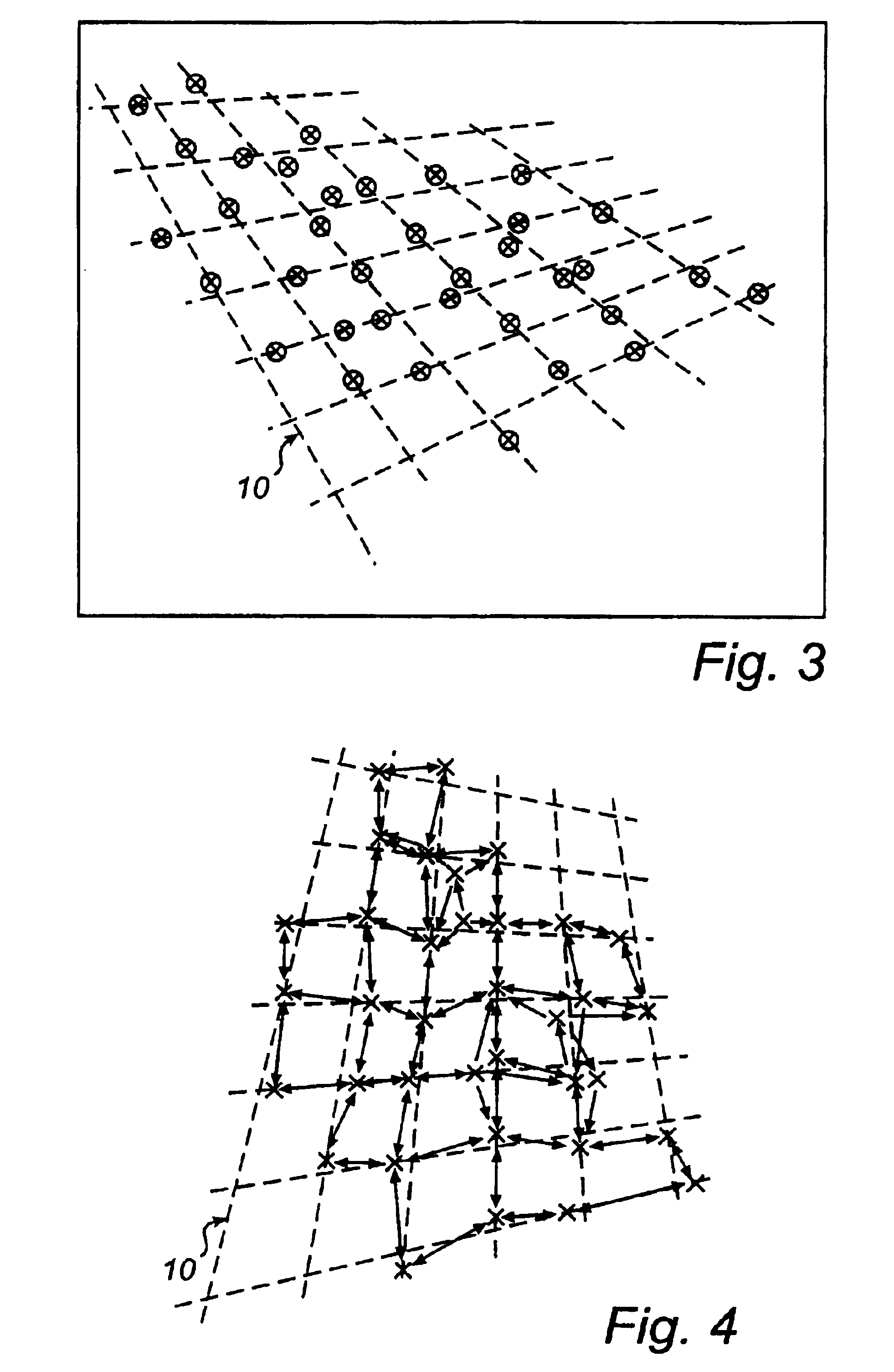
[0077]According to this reconstruction process, the data processor 25 carries out a regression adaptation of groups of points to straight lines which approximate raster lines, as is indicated in FIG. 10. More specifically, the points are grouped according to their raster positions. Thus, based on FIG. 8, vertical groups have been formed with points whose raster positions in a first dimension are given by −1, 0, 1, 2 and 3, and horizontal groups with points whose raster positions in a second dimension are given by −1, 0, 1, 2, 3 and 4. The direction of each individual line may have low precision on account of the small number of points per line, especially at the periphery of the selected component. Therefore, the data processor 25 carries out a supplementary regression adaptation in which the coefficient of inclination of the vertical and horizontal lines is adapted to a linear function in the horizontal and vertical directions. Perspective effects mean in fact that that mutually pa...

second embodiment

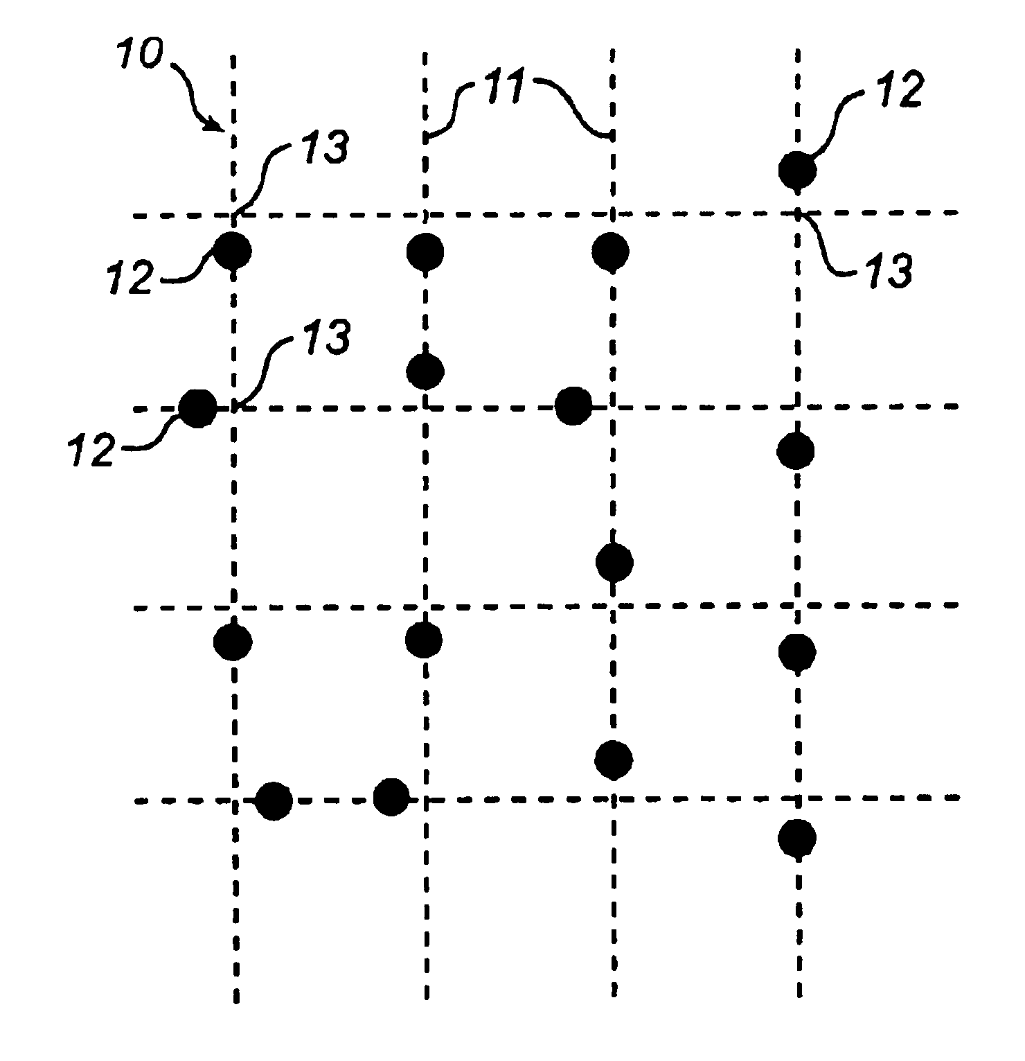
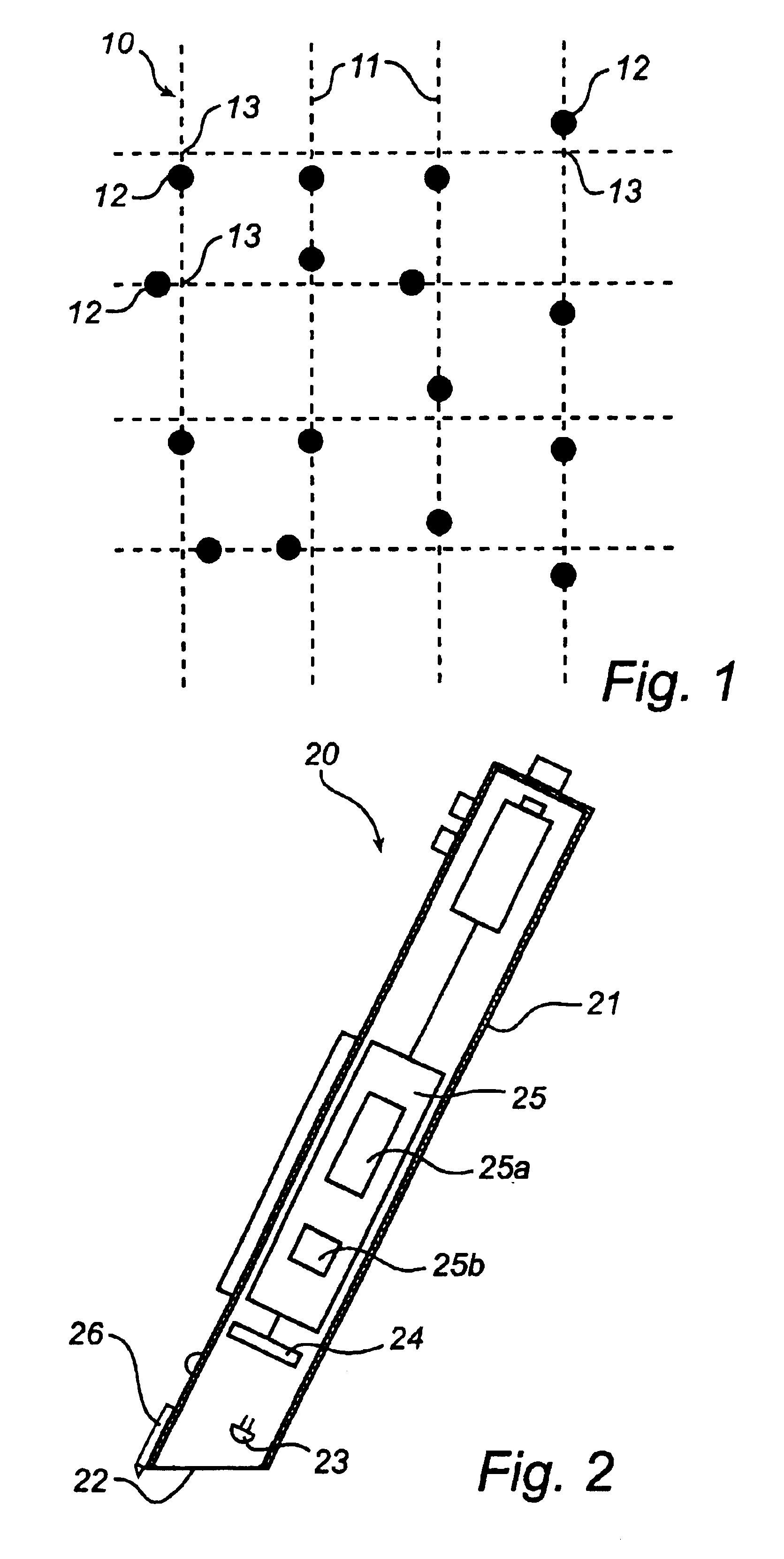
[0081]According to the reconstruction process, the data processor 25 carries out the reconstruction by computing a homogeneous transformation matrix. In this case, each point in the non-corrected binary image (FIG. 3) belonging to the selected component, as shown in FIG. 8, is compared with a corresponding raster intersection in an ideal raster, as shown in FIG. 12. Here, the raster positions are used to identify points and corresponding raster intersections, as is also indicated in FIGS. 8 and 12. A system of equations can thus be set up containing twelve unknown parameters (of the transformation matrix) and equations which in number are twice as many as the points in the selected component, in a manner similar to that described in “Digital Image Processing” by R. F. Gonzalez and R. E. Woods, Addison-Wesley, 1992, pp 67-68. Knowing that all points originate from one and the same geometric plane (i.e. the base), the number of unknown parameters can be reduced to eight.

[0082]There ar...


PUM


Abstract

A method aims at identifying, starting from objects in a digital image, a virtual raster included in a coding pattern. The objects in the image at least partially reproduce marks on a base, each mark being associated with a respective point of intersection of raster lines belonging to the virtual raster. The method comprises the steps of matching sets of objects against a cell unit, which corresponds to a recurring known basic element of said raster; when a set corresponds with the cell unit, identifying the objects in the set as approved; and reconstructing the virtual raster on the basis of the mutual arrangement of the approved objects. A computer program, a storage medium and a device for position determination are also described.

Description

[0001]This application claims priority on provisional Application No. 0104088-0 and 60 / 339,430 filed on Dec. 6, 2001 and Dec. 14, 2001, the entire contents of which are hereby incorporated by reference.FIELD OF THE INVENTION[0002]The present invention relates generally to identification of coding patterns in digital images. More particularly, the invention relates to a method, a computer program and a storage medium for use in reconstruction of a virtual raster included in such a coding pattern.[0003]The invention also relates to a device for decoding of positions from digital images of a coding pattern.BACKGROUND ART[0004]It is known to use a coding pattern to embed some type of information in a passive base such as a sheet of paper, a writing board or equivalent. A suitably programmed scanner, fax machine, camera or digital pen can then read, recreate and use the information embedded locally in the base. For example, graphical information on a base can be supplemented with embedde...

Claims


Application Information

Patent Timeline
IPC IPC(8): G09G5/10G09G5/00G06K7/10G06T3/00G06V10/20G06V30/142
CPCG06K7/14G06K9/22G06T3/00G06K2009/226G06V10/19G06V30/142G06V30/1423G06V10/247G06V10/20
Inventor PETTERSSON, MATS PETTER
Owner ANOTO AB
Why Eureka
Try Eureka