High force solenoid and solenoid-driven actuator

a solenoid and actuator technology, applied in the field of solenoid technology, can solve the problems of small gaps between pole pieces and armatures, and achieve the effect of significant operational improvement and enhanced operational improvemen

Inactive Publication Date: 2005-08-16
THOMAS MAGNETE GMBH
View PDF12 Cites 18 Cited by
  • Summary
  • Abstract
  • Description
  • Claims
  • Application Information

AI Technical Summary

Benefits of technology

[0027]The hydraulic valve actuator of this invention, with its improved solenoid as described above, provides significant operational improvement. The embodiments of the invention which combine t

Problems solved by technology

In each case, however, there is a long bearing surface which, as discussed above, can tend to add unwanted static friction, leading to possible hysteresis.
In certain of these prior devic

Method used


Image

  • High force solenoid and solenoid-driven actuator
  • High force solenoid and solenoid-driven actuator
  • High force solenoid and solenoid-driven actuator

Examples


Embodiment Construction

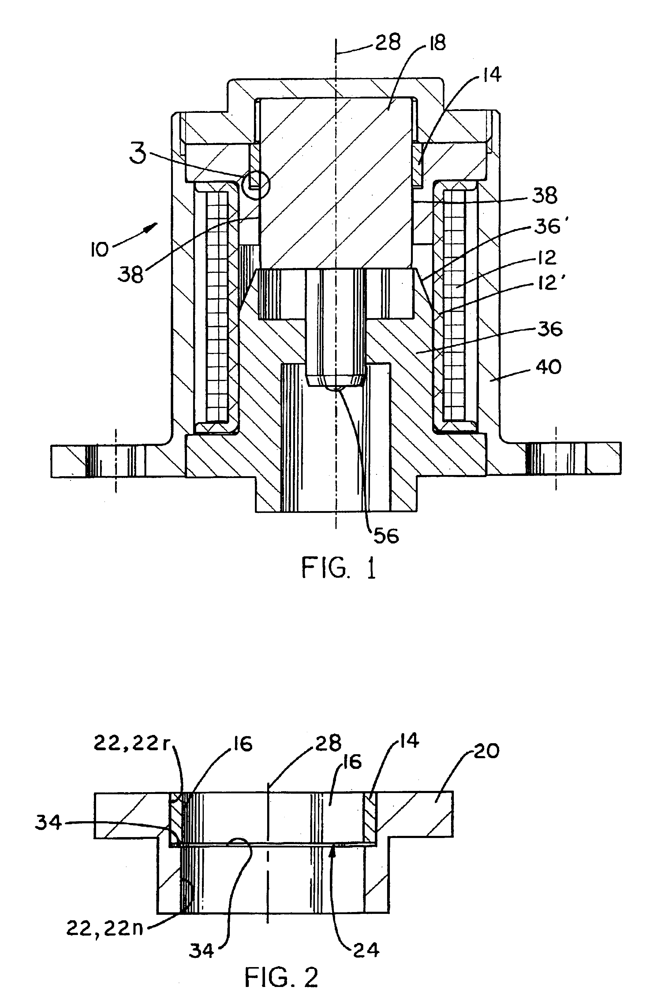
[0035]The figures illustrate preferred embodiments of this invention, FIG. 1 showing solenoid 10 and FIG. 5 showing a solenoid-driven hydraulic valve actuator 50 which is driven by solenoid 10.

[0036]Solenoid 10 and solenoid-driven valve actuator 50 are cylindrical; i.e., their major elements are generally axially-symmetric around centerline axis 28. Centerline axis 28 is the axis of the structures in each of FIGS. 1-3 and 5.

[0037]Solenoid 10 includes a coil 12 (wound on a bobbin 12′) and an armature 18. When coil 12 is energized with electrical current, it produces a magnetic field that exerts a force on armature 18 in a direction parallel to centerline axis 28. The general functionality of electromagnetic solenoids such as solenoid 10 is well-known to those skilled in the art and will not be described in detail herein.

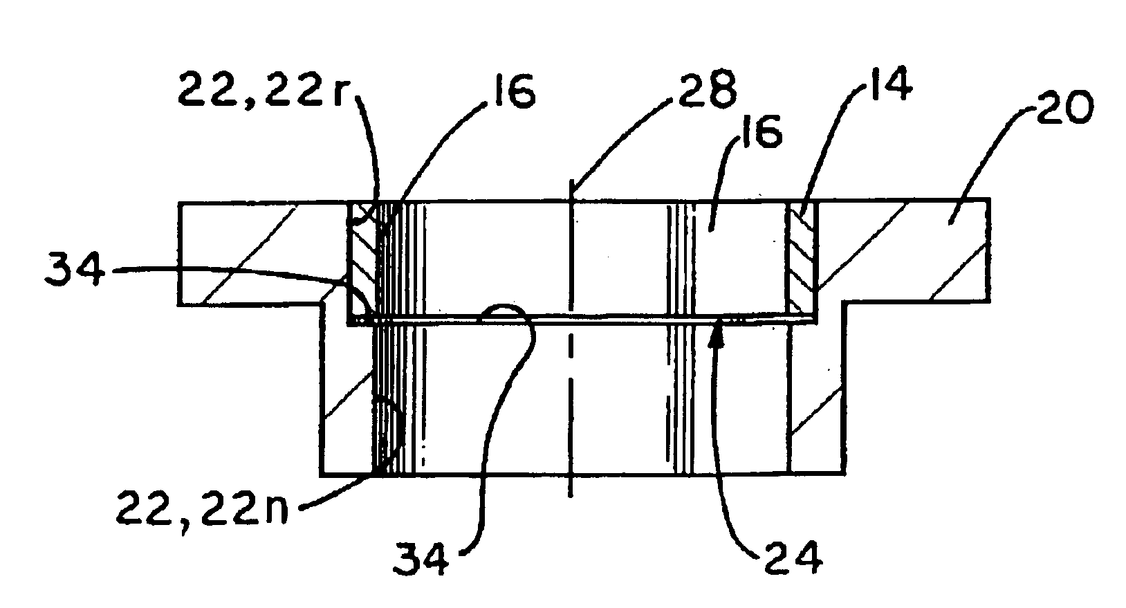
[0038]A first pole piece 20 of particular concern in this invention is used to direct the magnetic field produced by coil 12 and is part of a magnetic circuit which a...


PUM


Abstract

A solenoid having increased axial force and low static friction on the armature is disclosed and provides an improved solenoid-driven hydraulic valve actuator. The solenoid includes a coil member, a pole piece having an inside surface with recessed and non-recessed portions to form an inner recess in the pole piece, an armature inside the pole piece, and a bearing held in the recess between the pole piece and armature, the bearing having an inner surface extending inwardly just beyond the inside surface of the pole piece non-recessed portion.

Description

FIELD OF THE INVENTION[0001]This invention is related generally to solenoid technology, such as is used to drive actuators of various types. More particularly, the invention relates to the field of solenoid-driven hydraulic valve actuators for applications in which high solenoid force, rapid actuation, or extended actuator life are required.BACKGROUND OF THE INVENTION[0002]A number of advances in internal combustion engine technology include the application of solenoid-driven hydraulic valve actuators to provide more precise control over a number of engine functions such as control of the exhaust valves and fuel injectors. Hydraulic actuators used in applications such as these require the actuator to accelerate rapidly (have high axial output force), to be extremely reliable (i.e., operate for a great number of cycles during the life of the actuator assembly), and to have very low hysteresis.[0003]Thus, there is a need for solenoid-driven actuators which are fast-acting and precisel...

Claims


Application Information

Patent Timeline
IPC IPC(8): F16K31/06H01F7/13H01F7/08H01F7/16
CPCF16K31/0613H01F7/13H01F7/1607H01F7/081H01F2007/163
Inventor KIRSCH, BERNHARDMUSCHALLE, MANFRED
Owner THOMAS MAGNETE GMBH
Why Eureka
Try Eureka