Vehicle seat air conditioning system

Active Publication Date: 2005-08-16
DENSO CORP
View PDF8 Cites 89 Cited by
  • Summary
  • Abstract
  • Description
  • Claims
  • Application Information

AI Technical Summary

Benefits of technology

[0011]The present invention addresses the above disadvantages. Thus, it is an objective of the present invention to

Problems solved by technology

Thus, when the blower unit is driven to rotate, vibrations of the blower unit are likely conducted to the cushion member.
The conduction of vibrations of the blower unit to the cushion member disadvantageously causes deterioration in

Method used


Image

  • Vehicle seat air conditioning system
  • Vehicle seat air conditioning system
  • Vehicle seat air conditioning system

Examples


Example

(First Embodiment)

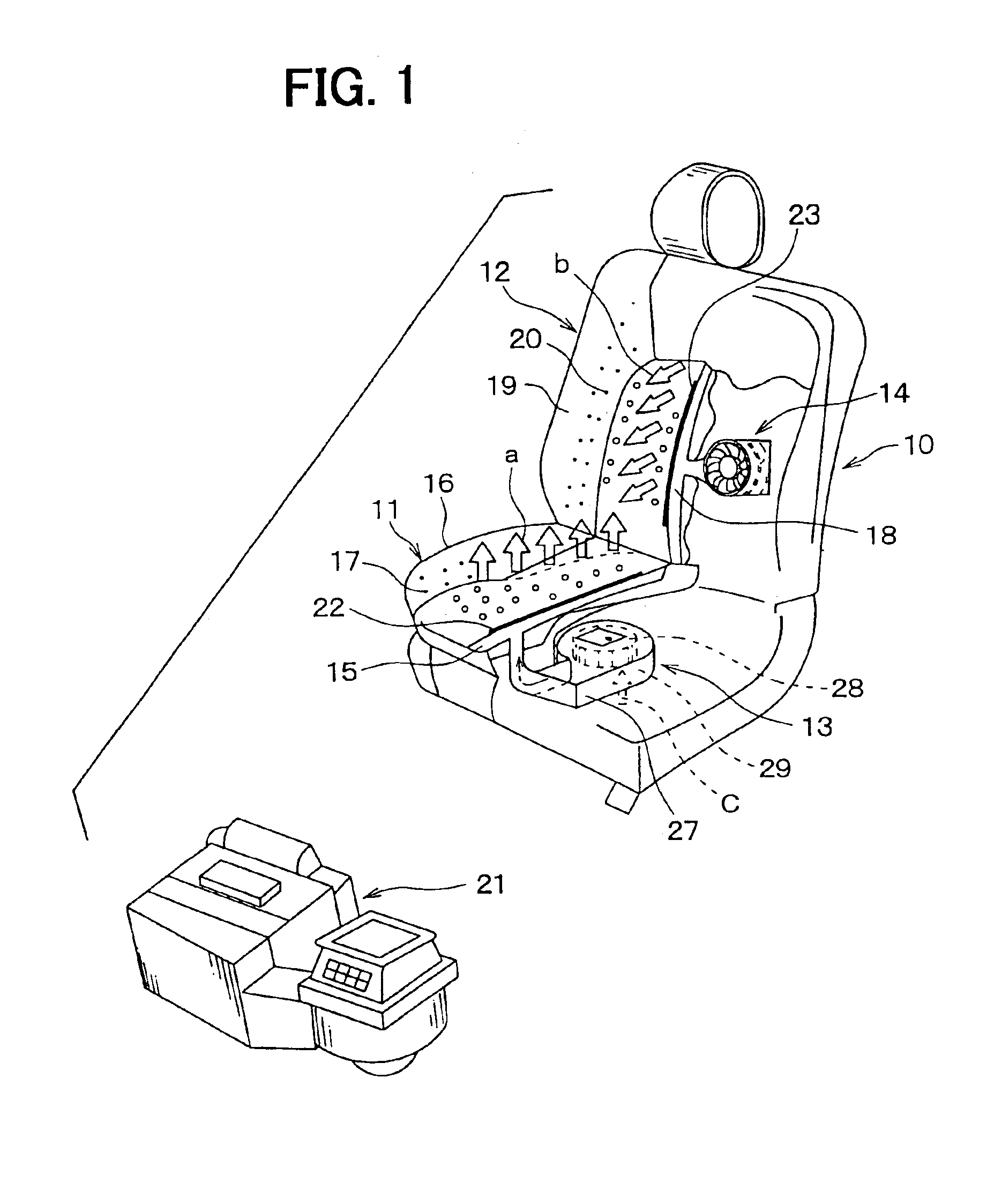
[0032]FIG. 1 shows a vehicle seat 10, which has a vehicle seat air conditioning system according to a first embodiment of the present invention. The vehicle seat 10 shown in FIG. 1 is practically used as a driver seat or front-passenger seat of a vehicle.

[0033]The vehicle seat 10 includes a seat cushion arrangement 11 and a seat back arrangement 12. The seat cushion arrangement 11 supports buttocks of an occupant (not shown) in the seat 10, and the seat back arrangement 12 supports a back of the occupant. First and second blower units 13, 14 are arranged in the seat cushion arrangement 11 and the seat back arrangement 12, respectively.

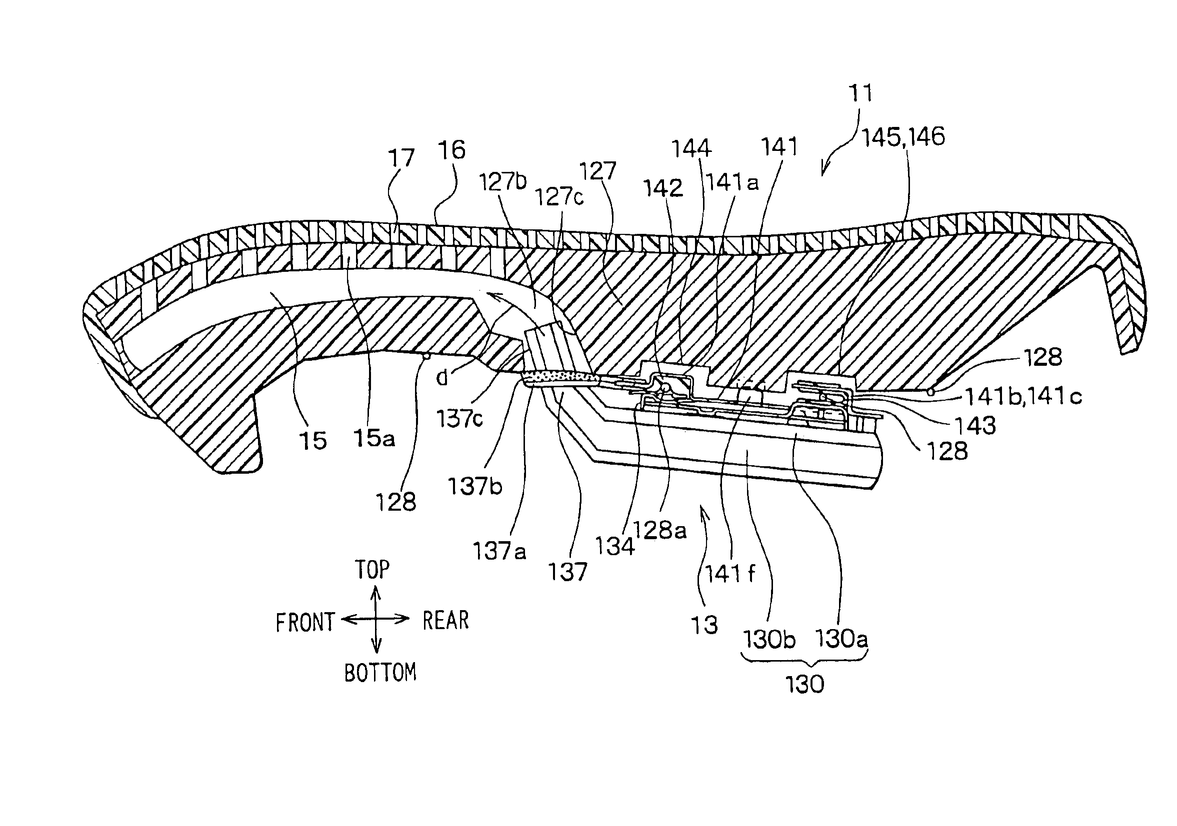
[0034]The first blower unit 13 draws air from a vehicle passenger compartment through a circular air intake opening 29 (FIG. 3) of the first blower unit 13 located at a lower side of the seat cushion arrangement 11. The air drawn from the air intake opening 29 is then conducted to a surface cover member 16 of the seat cushion arrangem...

Example

(Second Embodiment)

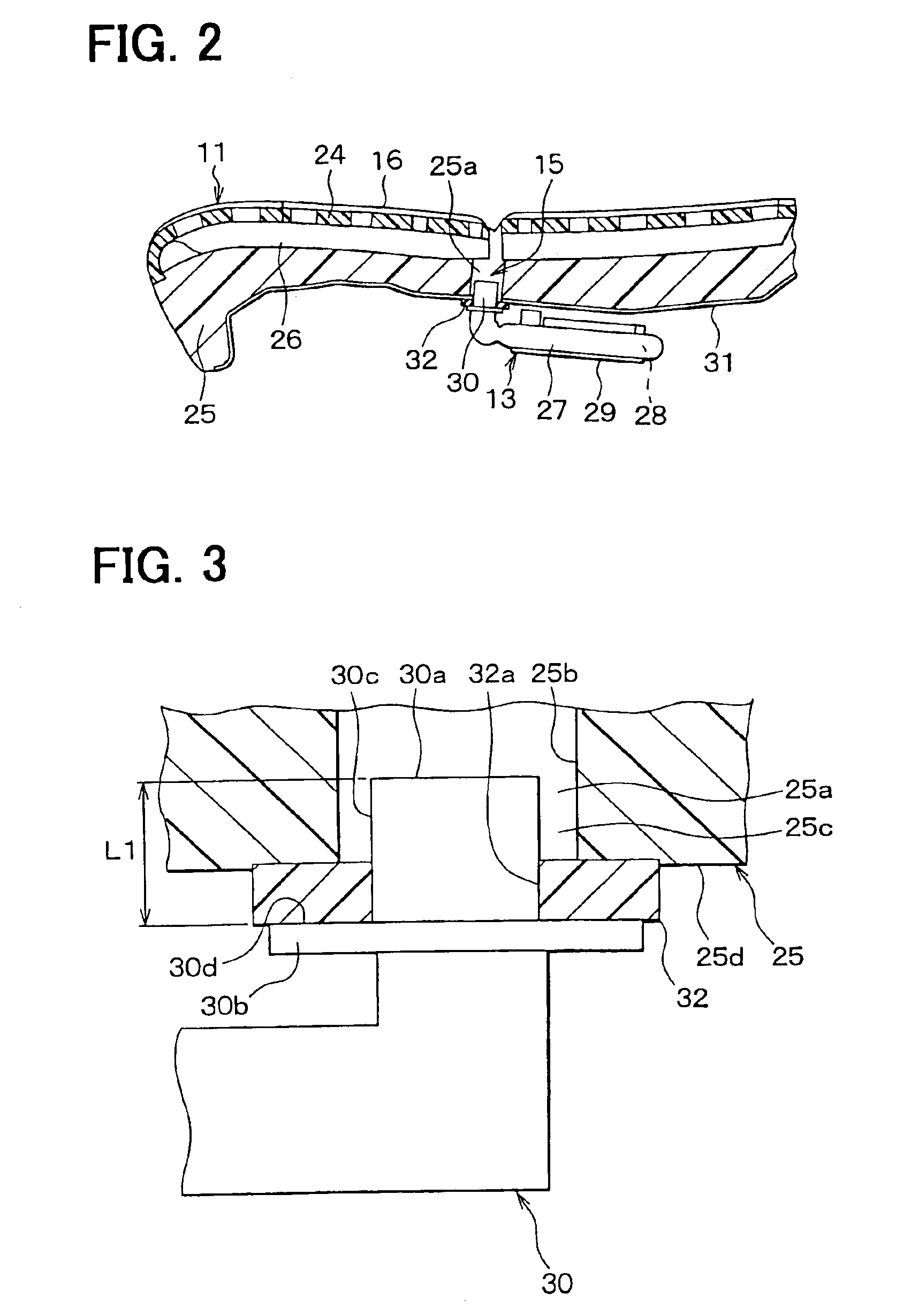
[0056]In the first embodiment, the buffering member 32 is provided to the end surface 25d of the cushion member 25, which is located on the first blower unit 13 side of the cushion member 25. In a second embodiment, as shown in FIG. 4, a cylindrical buffering member 32 is provided to the inner peripheral surface 25b of the through hole 25a. More specifically, the cylindrical buffering member 32 is radially positioned and is clamped between the distal end outer peripheral surface 30c of the discharge duct 30 and the inner peripheral surface 25b of the through hole 25a.

[0057]Here, the buffering member 32 can be air tightly adhered to the inner peripheral surface 25b of the through hole 25a by adhesive (not shown). Also, the buffering member 32 can be air tightly adhered to the outer peripheral surface 30c of the discharge duct 30 by adhesive (not shown).

Example

(Third Embodiment)

[0058]In the first and second embodiments, the buffering member 32 is used to restrain conduction of vibrations from the first blower unit 13 to the cushion member 25. In a third embodiment, as shown in FIG. 5, a damping flange (serving as a buffering member) 25e, which has an annular shape and projects radially inward in the through hole 25a is used in place of the buffering member 32 discussed in the first or second embodiment.

[0059]The damping flange 25e is formed integrally with the cushion member 25 and has a central through hole 25f in its center and a predetermined thickness, i.e., a vertical length in FIG. 5. The distal end outer peripheral surface 30c of the duct 30 is directly inserted into the central through hole 25f of the damping flange 25e.

[0060]The damping flange 25e does not necessarily mean the flange 25e that has the through hole 25f with a circular cross section but can be a flange that has a central through hole with an elliptic cross section,...


PUM


Abstract

A buffering member is connected between a cushion member and an air discharge duct of a blower unit to damp vibrations of the blower unit and thus to limit conduction of the vibrations from the blower unit to the cushion member. Resilient damper members are held between a connector bracket and a cover member and hold seat spring members, so that the blower unit is supported by the seat spring member. The connector bracket includes protrusions, which protrude toward the cushion member and hold the seat spring members through the resilient damper members. The cushion member includes recesses, which receive the protrusions of the connector bracket in such a manner that the protrusions are spaced from the cushion member.

Description

CROSS REFERENCE TO RELATED APPLICATION[0001]This application is based on and incorporates herein by reference Japanese Patent Application No. 2002-325607 filed on Nov. 8, 2002 and Japanese Patent Application No. 2003-272817 filed on Jul. 10, 2003.BACKGROUND OF THE INVENTION[0002]1. Field of the Invention[0003]The present invention relates to a vehicle seat air conditioning system installed in a vehicle seat.[0004]2. Description of Related Art[0005]Various vehicle seat air conditioning systems have been proposed. For example, one vehicle seat air conditioning system is disclosed in Unexamined Japanese Patent Publication No. 2000-152849. In the disclosed seat air conditioning system, a blower unit is placed inside or outside a cushion member of a vehicle seat, and an air discharge duct of the blower unit is directly inserted into an air intake passage section formed in the cushion member.[0006]In the disclosed seat air conditioning system, as described above, the air discharge duct is...

Claims


Application Information

Patent Timeline
IPC IPC(8): B60H1/00B60N2/56
CPCB60H1/00285B60N2/56B60H2001/00099B60H2001/003
Inventor AOKI, SHINJIKAMIYA, TOSHIFUMI
Owner DENSO CORP
Why Eureka
Try Eureka