Thick matter pump

a thick matter pump and pump body technology, applied in the direction of pump control, pump pump, positive displacement liquid engine, etc., can solve problems such as stroke shortening

Inactive Publication Date: 2005-08-16
PUTZMEISTER ENG
View PDF14 Cites 25 Cited by
  • Summary
  • Abstract
  • Description
  • Claims
  • Application Information

AI Technical Summary

Benefits of technology

[0008]Beginning therewith, it is the task of the invention to provide a sensor arrangement in a thick material pump of the type described in the above intr

Problems solved by technology

The correction sensor thereby has the task, of carrying out an automatic stroke correction, when the drive piston in the concerned drive cylinder no

Method used


Image

  • Thick matter pump
  • Thick matter pump
  • Thick matter pump

Examples


Embodiment Construction

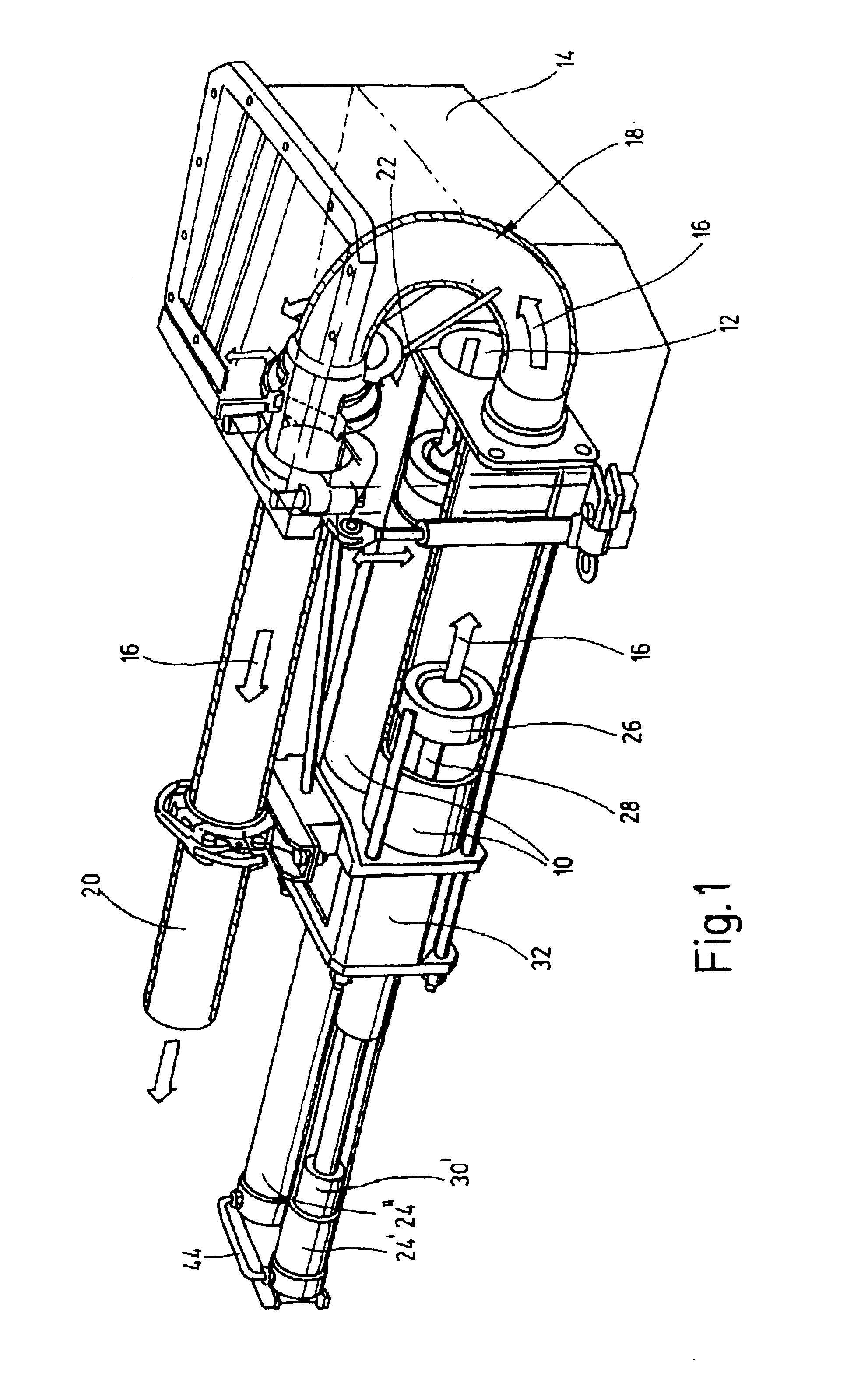
[0022]The thick material pump shown in FIG. 1 is comprised essentially of two delivery cylinders 10, of which openings 12 at one end communicate alternatingly with a material feed basin 14, which during the pressure stroke (arrow 16) are connectable via a pipe switch 18 with a transfer line 20 and during the suction stroke (arrow 22) are open towards the material feed basin 14 with suctioning in of material. The delivery cylinders 10 are driven in counter-stroke via the hydraulic drive cylinders 24′, 24″. For this purpose the delivery pistons 26 are connected via a common piston rod 28 with the drive pistons 30′, 30″ of the drive cylinders 24′, 24″. In the area between the delivery cylinders 10 and the drive cylinders 24′, 24″ there is a water box 32, through which the piston rods 28 extend.

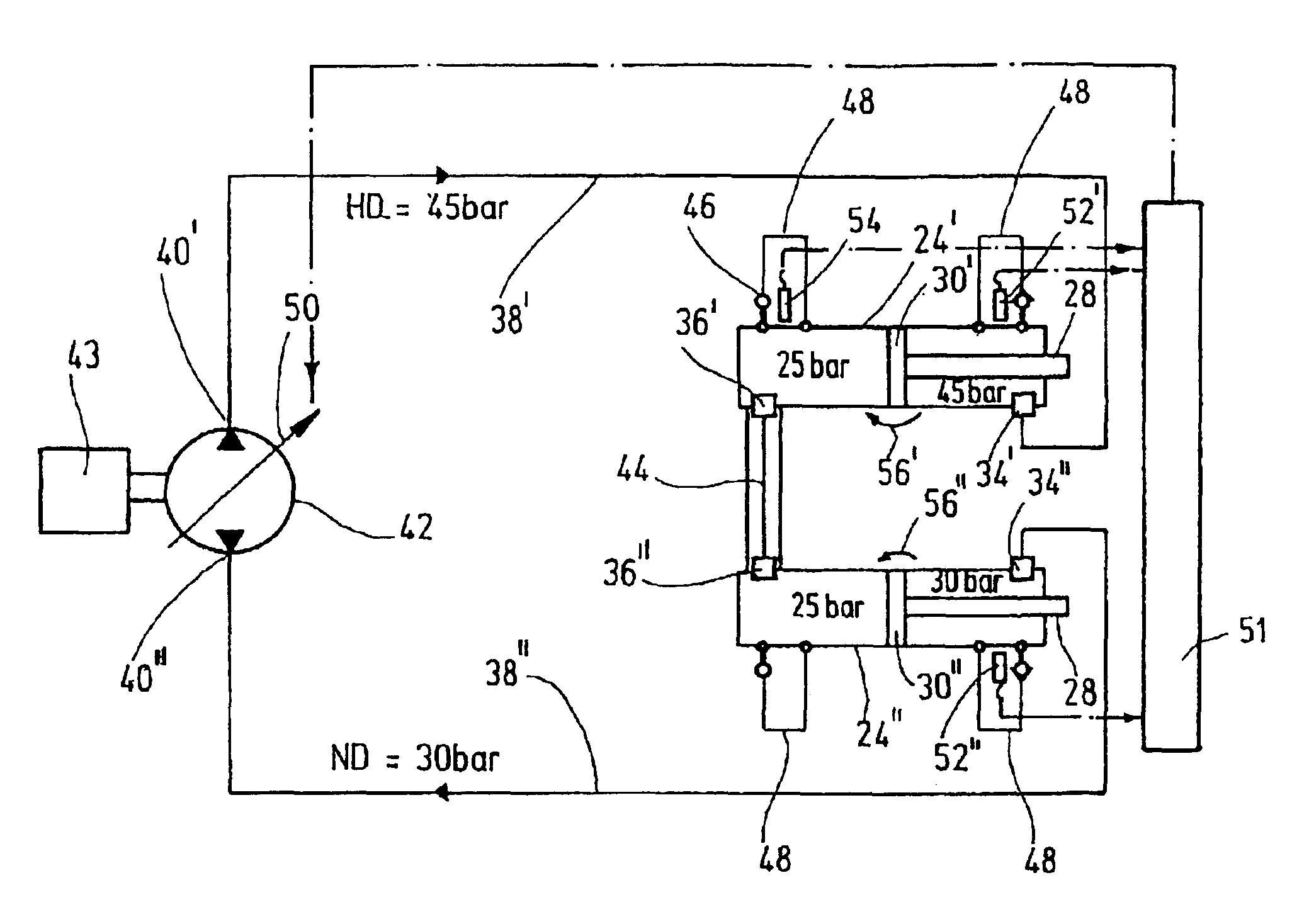
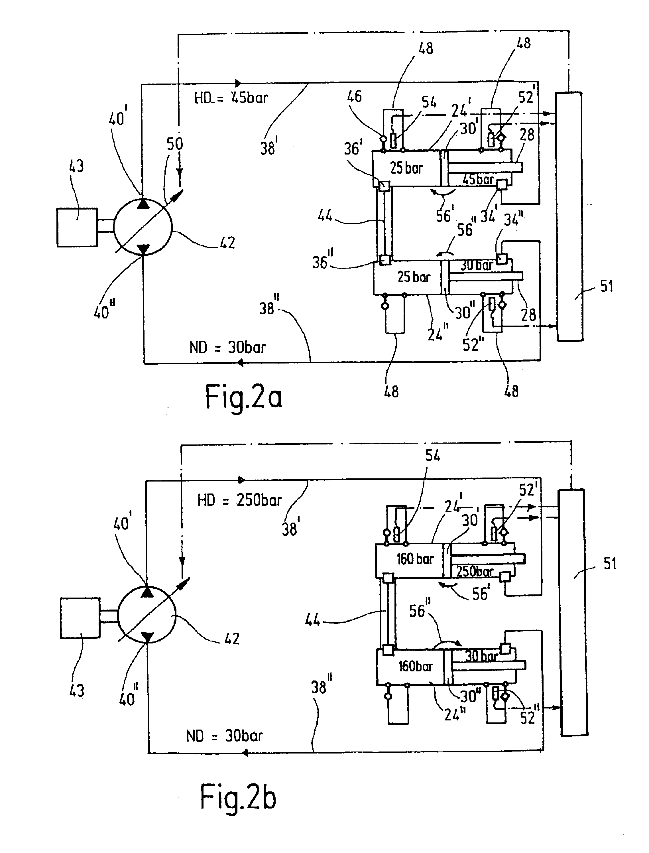
[0023]The drive cylinders 24′, 24″ are connected at piston rod sided connections 34′, 24″ (FIGS. 2a,b) or piston head sided connections 36′36″ (FIGS. 3a,b) via pressure lines 38′, 38″ with the hy...


PUM


Abstract

In a thick matter pump, especially for delivering concrete, comprising two delivery cylinders, it is known to provide two position sensors in one of the two cylinders for control of the pistons. However, leakage of hydraulic fluid can lead to an imbalance of the two cylinders. In the invention two position sensors (52′, 52″) are provided, which are arranged at a defined distance from one of the ends of the drive cylinders and which respond to a drive piston (30′, 30″) that is passing by. To prevent the formation of concrete clots inside the delivery cylinders (10) and to prevent the occurrence of a slamming when the drive pistons (30′, 30″) reach their end of travel, the invention provides that both position sensors (52′, 52″) are arranged at a distance from the piston rod-side ends of both drive cylinders (24′, 24″) and, in addition, a correcting sensor (54) is arranged at a defined distance from the piston head-side end of one of the drive cylinders (24′). This correcting sensor can be temporarily activated for initiating a reversing process overruling the rod-side position sensor (52″) of the other drive cylinder (24″).

Description

CROSS REFERENCE TO RELATED APPLICATION[0001]This application is a national stage of PCT / EP01 / 07415 filed Jun. 28, 2001 and based upon DE 100 36 202.8 filed Jul. 24, 2000 under the International Convention.BACKGROUND OF THE INVENTION[0002]1. Field of the Invention[0003]The invention concerns a thick matter pump, with two delivery cylinders communicating with a material feed basin via openings situated on an end face, with two hydraulic drive cylinders connected to a reversible hydraulic pump via connections at the piston rod side or piston head side, with a swing oil line connecting the drive cylinder ends opposite to the pump with each other, the drive pistons of the drive cylinders and the delivery pistons of the delivery cylinders being pair-wise rigidly connected with each other via common piston rods, with equalizing lines connected in the area of the two ends of the drive cylinders bridging over the drive pistons at their respective end positions and containing a check or back ...

Claims


Application Information

Patent Timeline
IPC IPC(8): F04B9/117F04B9/00F04B15/02F04B15/00F04B9/105F04B9/111F04B49/00F04B9/113F04B23/06
CPCF04B9/1178F04B15/023F04B15/02
Inventor MUNZENMAIER, WERNERPETZOLD, WOLF-MICHAEL
Owner PUTZMEISTER ENG
Why Eureka
Try Eureka