Valve assembly for reciprocating compressors

a compressor and valve assembly technology, applied in the direction of pump components, positive displacement liquid engines, liquid fuel engine components, etc., can solve the problems of high-frequency noise, generating operational impact and noise, and the conventional valve assembly for reciprocating compressors is problematic, so as to achieve the effect of simple assembly into a single body

Inactive Publication Date: 2005-08-16
SAMSUNG GWANGJU ELECTRONICS CO LTD
View PDF7 Cites 4 Cited by
  • Summary
  • Abstract
  • Description
  • Claims
  • Application Information

AI Technical Summary

Benefits of technology

[0011]Accordingly, it is an aspect of the present invention to provide a valve assembly for re

Problems solved by technology

However, the conventional valve assembly for reciprocating compressors is problematic, as follows.
Therefore, the free end of the reed valve repeatedly strikes against the stopper and the exhaust hole plate during the rectilinear reciprocating m

Method used


Image

  • Valve assembly for reciprocating compressors
  • Valve assembly for reciprocating compressors
  • Valve assembly for reciprocating compressors

Examples


Embodiment Construction

[0032]Reference will now be made in detail to the present preferred embodiments of the present invention, examples of which are illustrated in the accompanying drawings, wherein like reference numerals refer to like elements throughout.

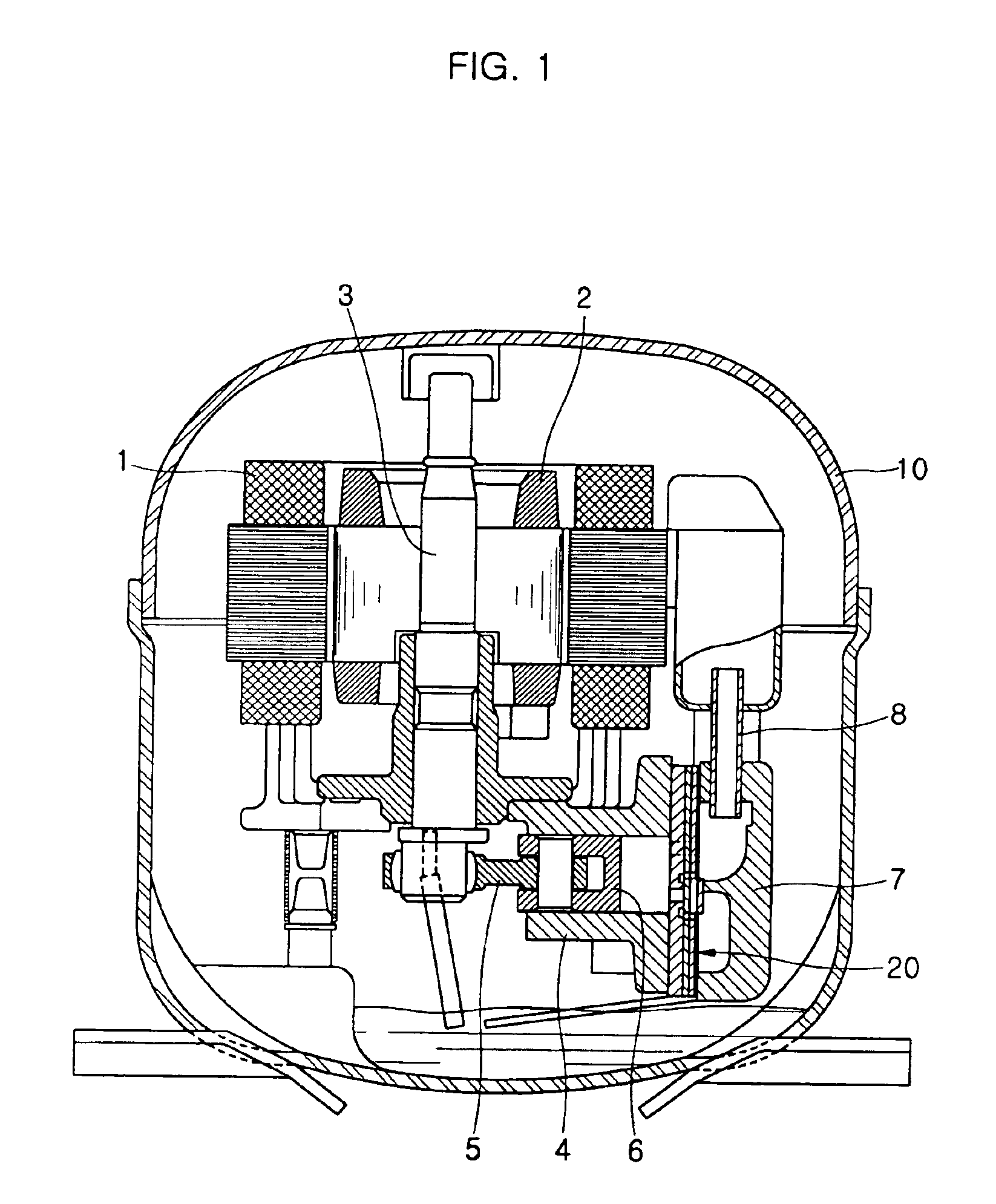
[0033]FIG. 1 is a longitudinal sectional view of a reciprocating compressor having a valve assembly, according to an embodiment of the present invention. As shown in the drawing, the reciprocating compressor of the present invention includes a plurality of elements, that is, a stator 1, a rotor 2, a crankshaft 3, a cylinder 4, a piston 6, and a cylinder head 7, which are hermetically housed in a hermetic casing 10. The stator 1 and the rotor 2 are installed in the hermetic casing 10, such that the stator 1 is immobile, while the rotor 2 is rotatable. The crankshaft 3 is axially inserted into the rotor 2 to rotate along with the rotor 2. The cylinder 4 defines a compression chamber therein. The piston 6 is received in the cylinder 4, and is connected t...


PUM


Abstract

A valve assembly for the reciprocating compressors, elements of which are easily and simply assembled into a single body, and which reduces operational impact and noise caused by an operation of a reed valve, thus allowing a silent operation of the reciprocating compressors. The valve assembly includes an exhaust hole plate having an exhaust hole, a reed valve plate having a reed valve, a stopper plate having a stopper, and a pressure unit formed on a lower surface of a cylinder head, wherein the exhaust hole plate, the reed valve plate and the stopper plate are assembled with the cylinder together with the cylinder head when the cylinder head is mounted to the cylinder. The stopper is bent at a junction end thereof at a predetermined angle of inclination, so that a free end of the stopper is raised toward the cylinder head. The pressure unit includes a first pressure projection to compress the junction end of the stopper, a second pressure projection to compress the free end of the stopper, and a third pressure projection to compress an intermediate point of the stopper between the junction and free ends. The stopper is thus supported while being shaped into a bow shape at a position between the cylinder head and the exhaust hole plate.

Description

CROSS-REFERENCE TO RELATED APPLICATION[0001]This application claims the benefit of Korean Application No. 2003-21822, filed Apr. 8, 2003, in the Korean Intellectual Property Office, the disclosure of which is incorporated herein by reference.BACKGROUND OF THE INVENTION[0002]1. Field of the Invention[0003]The present invention relates, in general, to reciprocating compressors and, more particularly, to a valve assembly for the reciprocating compressors, elements of which are easily and simply assembled into a single body, and which reduces operational impact and noise caused by an operation of a reed valve, thus allowing a silent operation of the reciprocating compressors.[0004]2. Description of the Related Art[0005]As well known to those skilled in the art, a reciprocating compressor includes a plurality of elements, that is, a stator, a rotor, a crankshaft, a cylinder, a piston, and a cylinder head, which are hermetically housed in a hermetic casing. The stator and the rotor are in...

Claims


Application Information

Patent Timeline
IPC IPC(8): F04B39/10
CPCF04B39/1073F04B39/10
Inventor SEO, SEUNG DON
Owner SAMSUNG GWANGJU ELECTRONICS CO LTD
Why Eureka
Try Eureka