
Juicer

a technology of juicer and juicing rod, which is applied in the field of juicer, can solve the problems of affecting the use of the juicer, so as to reduce the failure rate, reduce the number of parts, and simplify the construction.

Active Publication Date: 2015-06-18
HUROM CO LTD
View PDF6 Cites 19 Cited by
  • Summary
  • Abstract
  • Description
  • Claims
  • Application Information

AI Technical Summary

Benefits of technology

The present invention provides various technical effects that are beneficial for users, regardless of whether the inventor knows about these effects or not. These effects can be realized by using the invention or its components in a certain way. Some additional effects may be expected and can be realized by those skilled in the art, based on the description.

Problems solved by technology

When continuously making juices using such conventional home juicers, residue is held in net holes of strainers of the juicers and inconveniences users when they are making the desired amount of juice.
Further, to remove the residue from the net holes of the strainers, users are required to frequently disassemble the juicers and to wash out the disassembled parts of the juicers, which causes inconvenience.
Further, the conventional home juicers do not allow highly viscous juices to easily flow down through the strainers which also inconveniences users.
When the juice extractor having the complicated gear mechanism is used for a lengthy period of time, various problems may occur as follows.
First, due to abrasion or breakage of the gears, the failure rate of the juice extractor increases.
Further, in the juice extractor, the three kinds of gears must be assembled with each other in such a way that they can be rotated simultaneously in a state in which they are exactly and precisely engaged with each other, so that it is not easy to assemble the gears of the juice extractor.
However, the patented invention is problematic in that, although dirt is held and accumulated in gaps between teeth of the gears, it is not easy to wash out the dirt from the gaps between the teeth of the gears.
Particularly, the intermediate gear that is fixed to the bottom of the housing cannot be disassembled from the housing so that it is impossible to remove the residue or dirt held in the gaps between the teeth of the gears, thereby causing serious problems for the maintenance of the cleanliness of the juice extractor.

Method used


Image

  • Juicer
  • Juicer
  • Juicer

Examples


Embodiment Construction

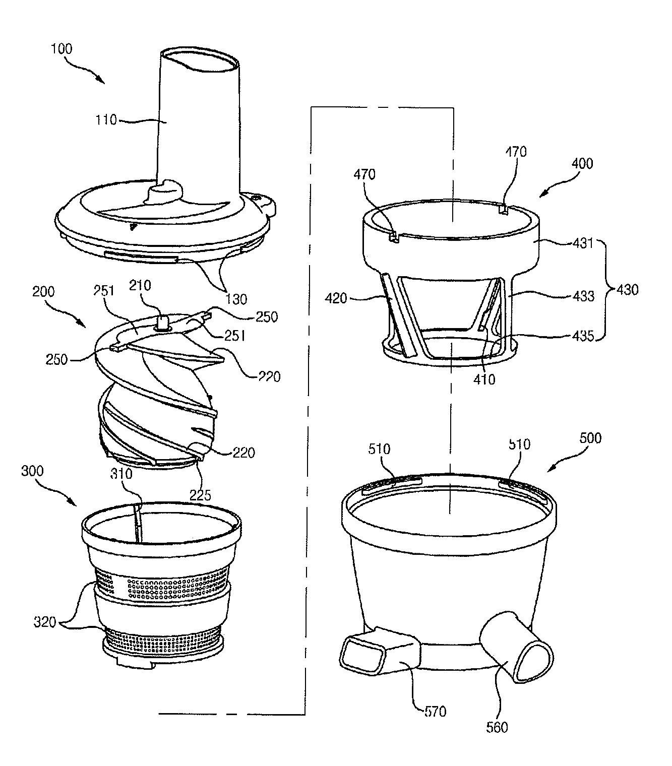
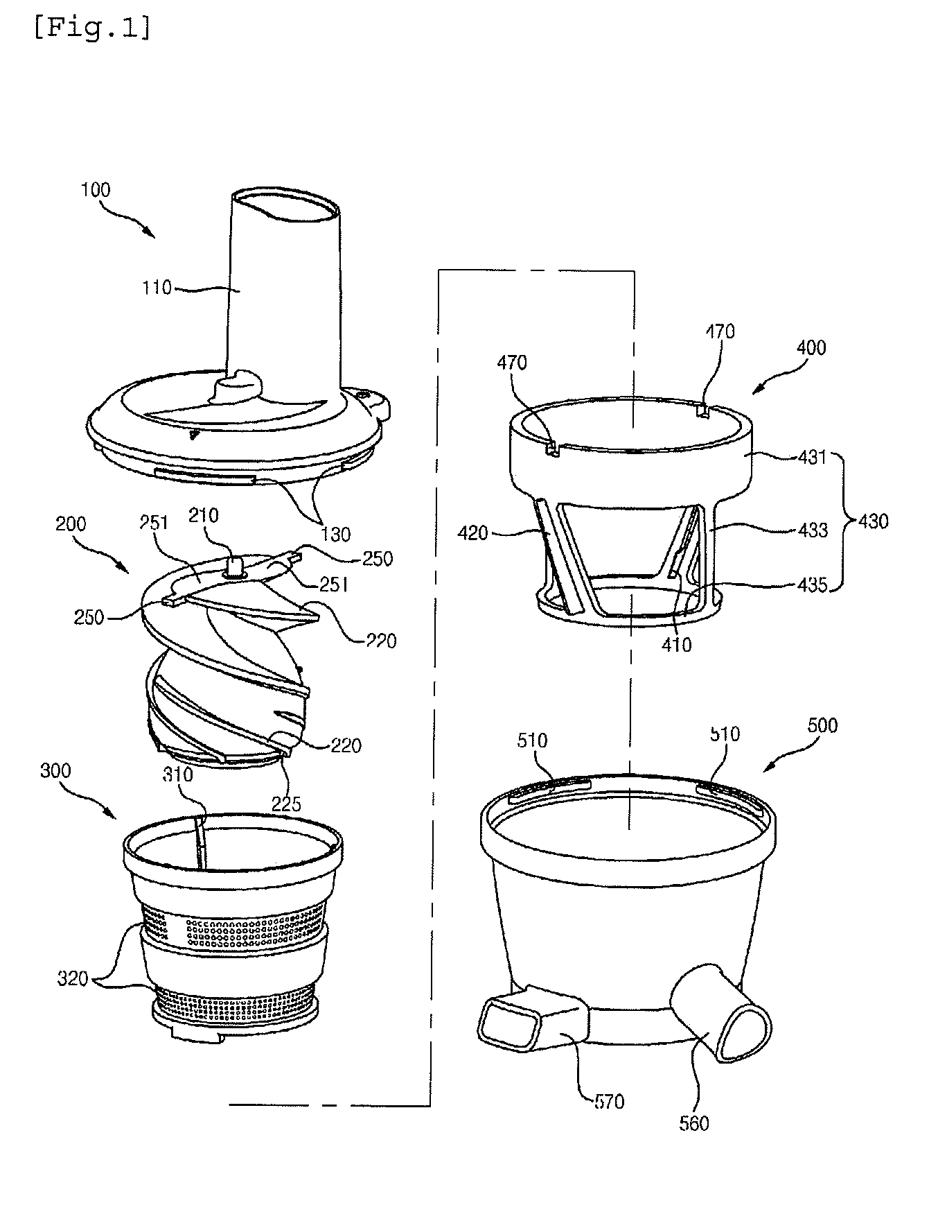
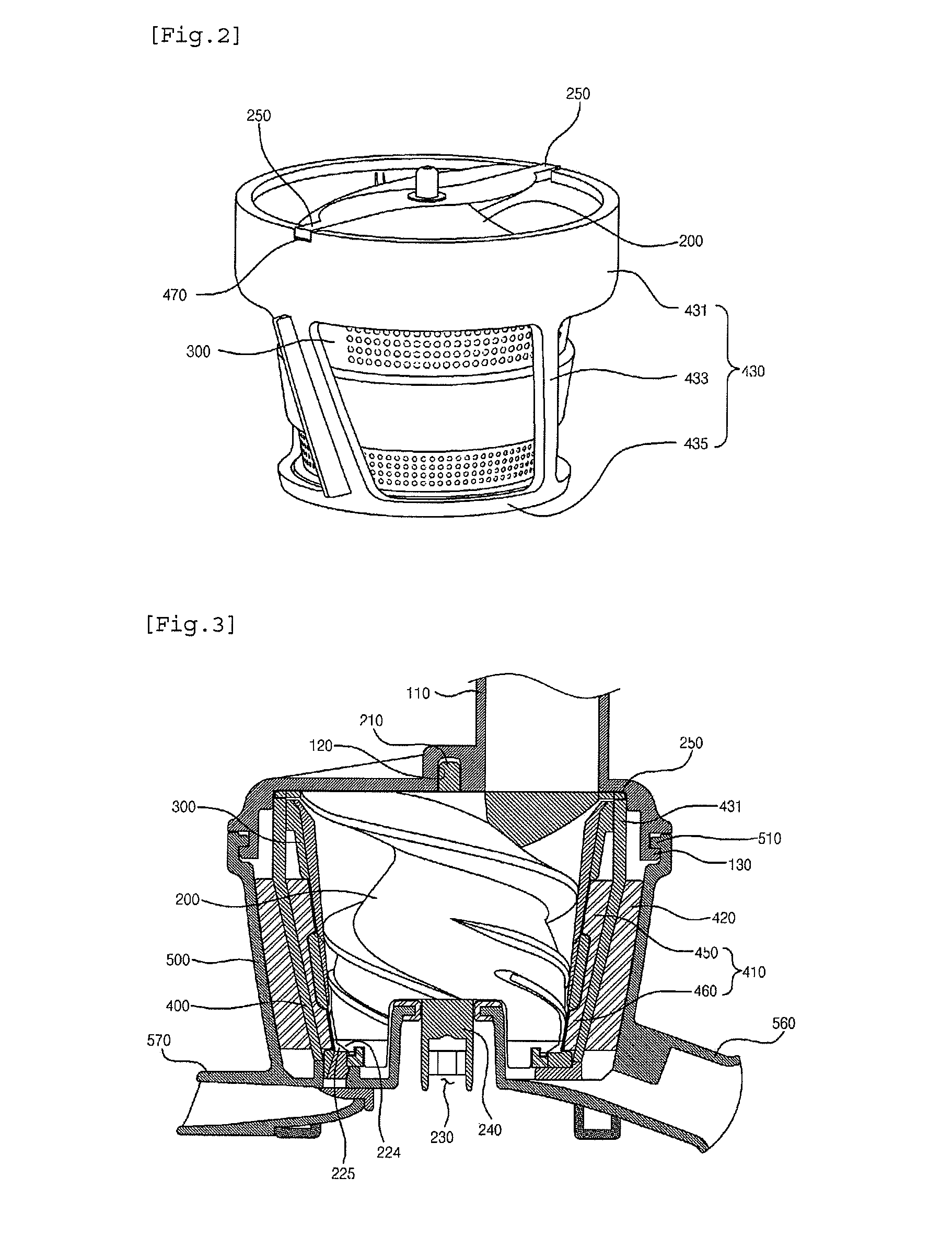
[0053]Hereinafter, the preferred embodiment of the present invention will be described in detail with reference to the accompanying drawings. The terminologies or words used in the description and the claims of the present invention should not be interpreted as being limited merely to their common and dictionary meanings. On the contrary, they should be interpreted based on the meanings and concepts of the invention in keeping with the scope of the invention based on the principle that the inventor(s) can appropriately define the terms in order to describe the invention in the best way.

[0054]It is to be understood that the form of the invention shown and described herein is to be taken as a preferred embodiment of the present invention, so it does not express the technical spirit and scope of this invention. Accordingly, it should be understood that various changes and modifications may be made to the invention without departing from the spirit and scope thereof.

[0055]As shown in FI...


PUM


Abstract

The present invention relates to a juicer comprising a screw is arranged inside a net drum, and a rotary brush placed between an inner wall of a housing and an outer wall of the net drum, wherein a screw coupling protrusion or a screw coupling groove is formed on the upper part of the screw and a rotary brush coupling groove or a rotary brush coupling protrusion is formed on the upper part of the rotary brush such that the screw coupling protrusion and the rotary brush coupling groove are coupled or the screw coupling groove and the rotary brush coupling protrusion are coupled in such a manner that the rotary brush is directly rotated by the screw.

Description

BACKGROUND OF THE INVENTION[0001]1. Technical Field[0002]The present invention relates to a juicer, in which a rotary brush is configured to be directly rotated by a feed screw, thereby reducing the failure rate caused by breakage or abrasion of parts, such as gears, and which can be easily and simply assembled and used, and the parts of which can be washed easily and simply, thereby being always in a clean and hygienic condition, and which can easily discharge residue, thereby easily performing the juice extracting operation, and which prevents residue from contaminating juice, thereby improving the quality of juices.[0003]2. Background Art[0004]In recent years, as the interest in healthy living has increased and with the increased awareness of the harmfulness of various additives that are added to beverages, such as juice or soybean milk, many people have begun to prepare vegetable juice, fruit juice or grain juice at home from fresh vegetables, fruits or grains. Thus, juicers for...

Claims


Application Information

Patent Timeline
Patent Type & Authority Applications(United States)
IPC IPC(8): A23N1/02
CPCA23N1/02A47J19/02A47J19/025A47J19/06
Inventor KIM, YOUNG KI
Owner HUROM CO LTD
Learn More