
Apparatus and method for replacing aortic valve

a technology for aortic valves and apparatuses, applied in the field of apparatus and methods for performing cardiac surgery, can solve the problems of serious deleterious effects on patients caused by the use of heart-lung machines, and it is effectively impossible to perform the required surgery off the pump using conventional apparatus and methods

Inactive Publication Date: 2005-08-16
MEDTRONIC INC
View PDF71 Cites 329 Cited by
  • Summary
  • Abstract
  • Description
  • Claims
  • Application Information

AI Technical Summary

Benefits of technology

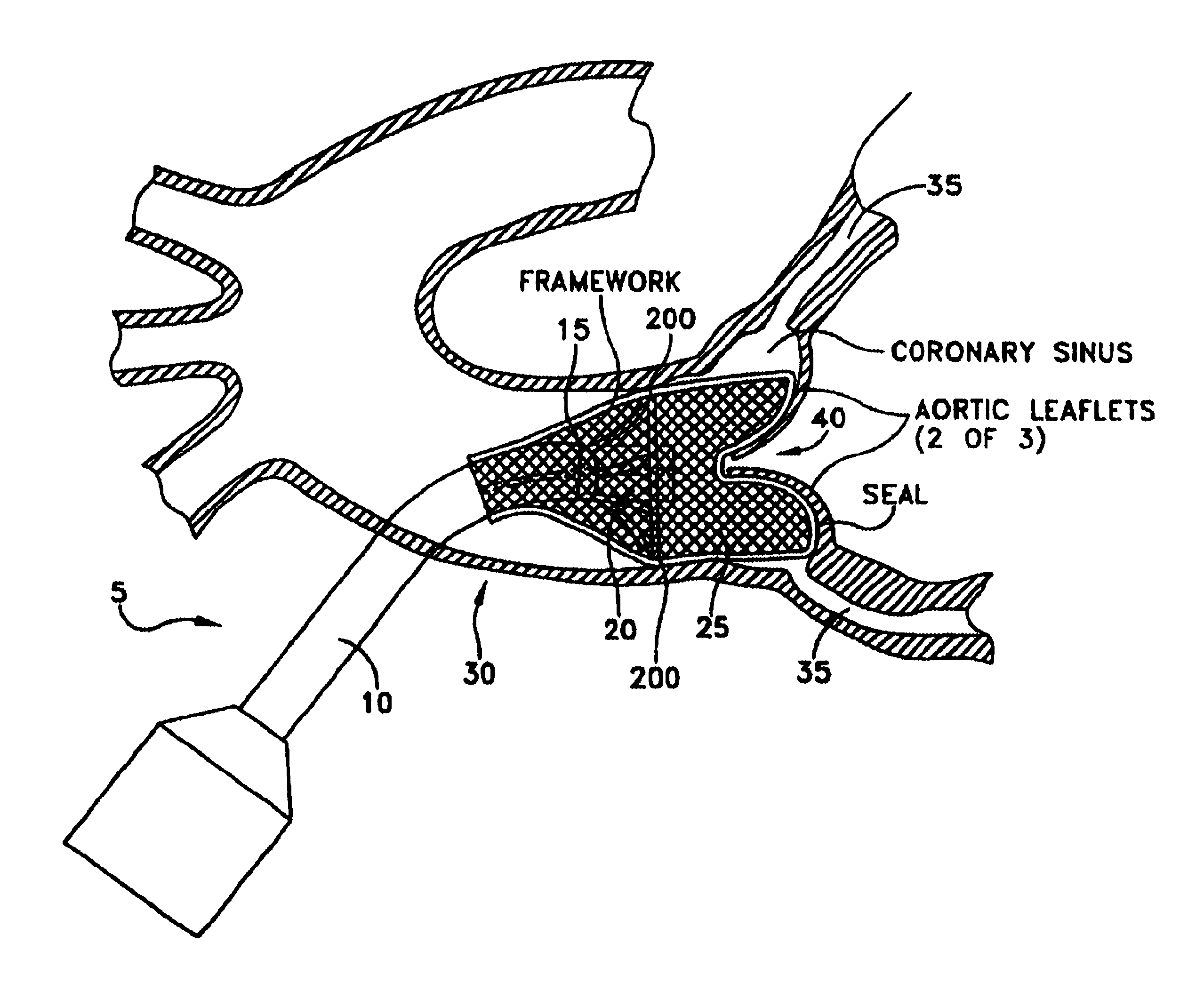
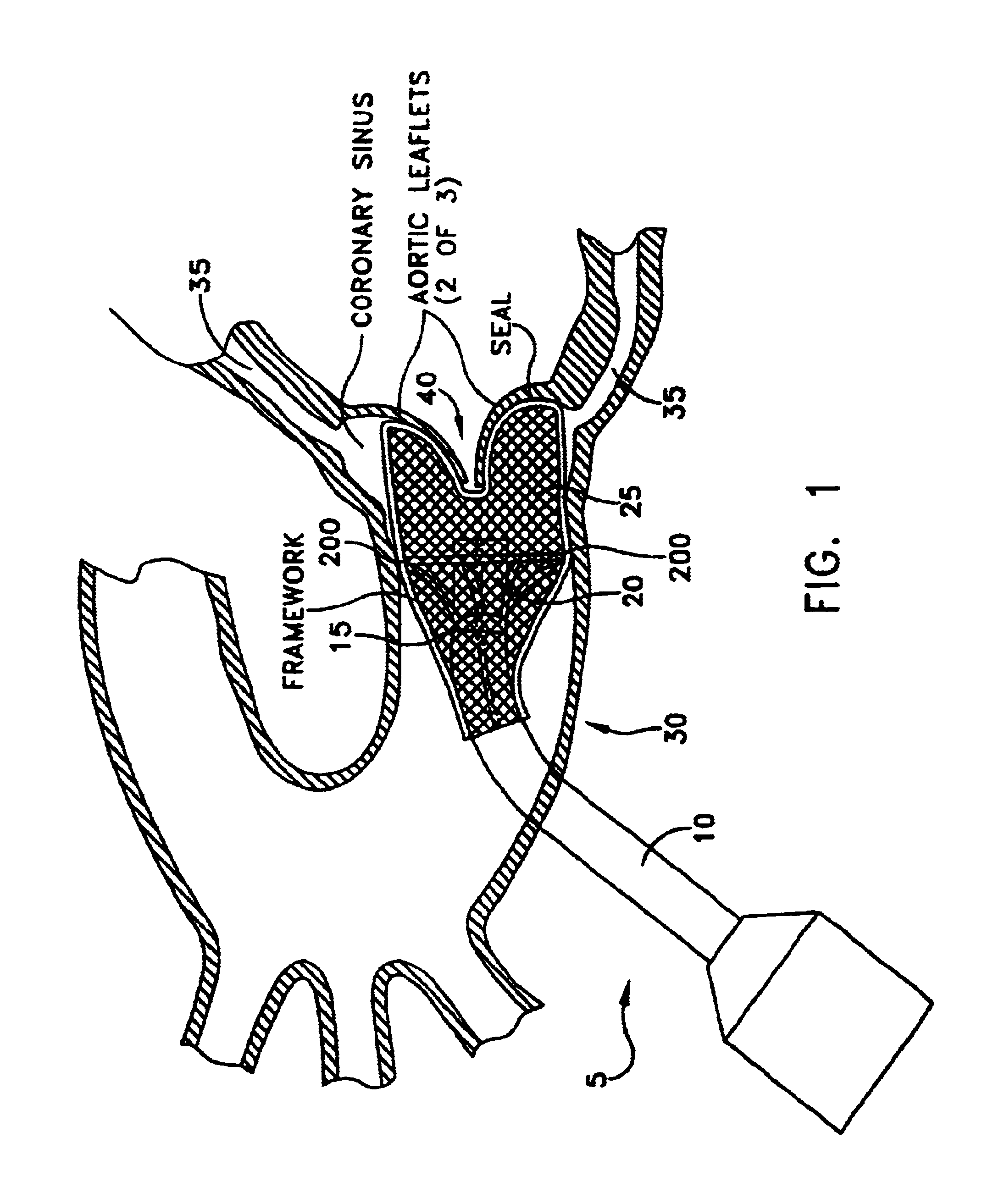
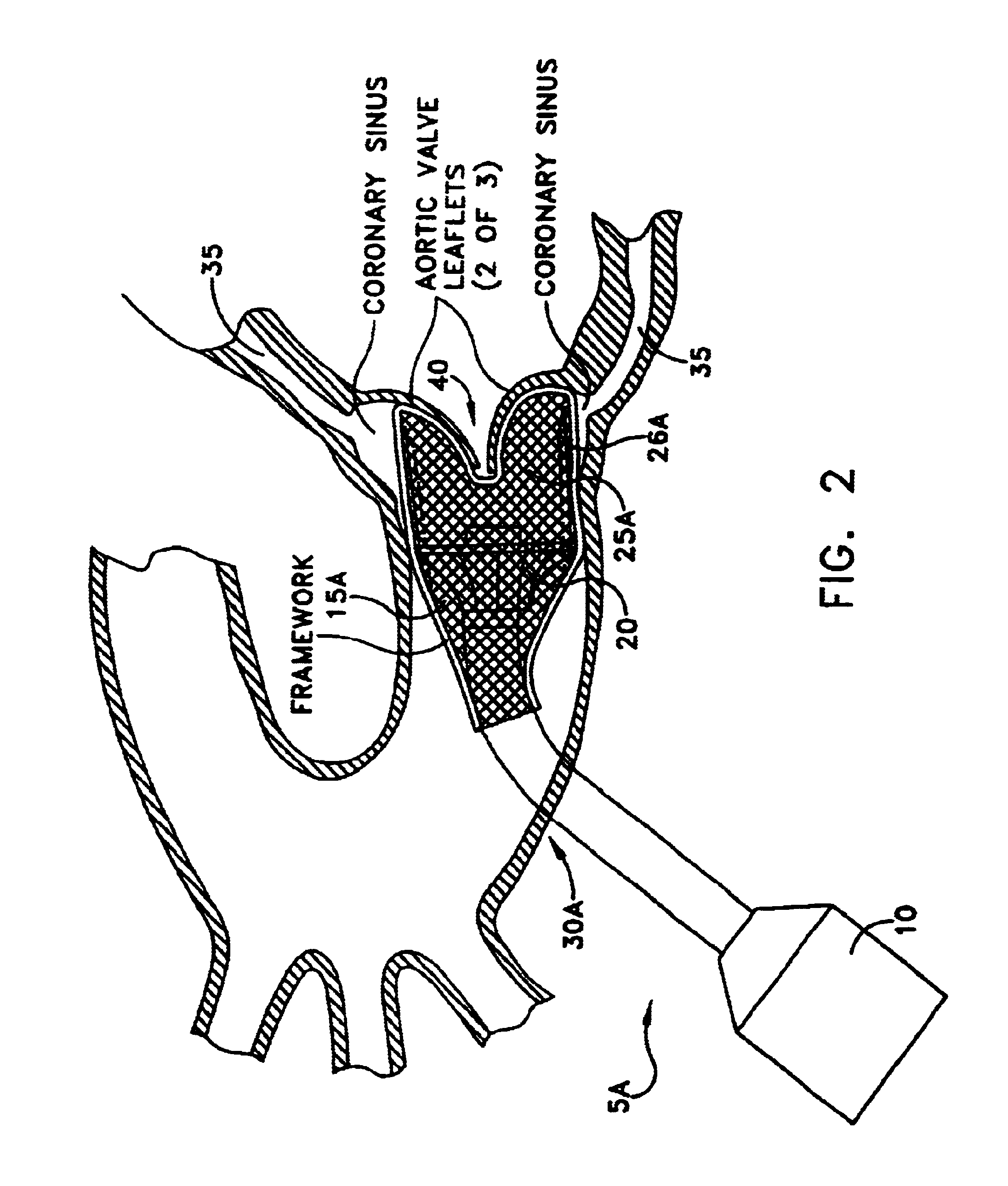
[0010]These and other objects are achieved through the provision and use of novel apparatus which, in one preferred form of the invention, comprises a cannula; an aortic filter connected to the cannula; a check valve connected to the cannula distally of the aortic filter; and a coronary artery filter connected to the cannula and extending distally of the check valve. During use, the apparatus is deployed in the aorta so that the coronary artery filter covers the openings (coronary ostia) of the coronary arteries, the check valve is deployed downstream from the coronary artery filter, and the aortic filter is deployed downstream from the check valve. Among other things, in addition to delivering the aortic filter, check valve and coronary artery filter to the surgical site and supporting them there, the cannula also permits the delivery of instruments to the surgical site.

Problems solved by technology

However, it has been recognized that the use of a heart-lung machine can have serious deleterious effects on the patient.
However, for some types of procedures, e.g., aortic valve replacement, it can be effectively impossible to conduct the required surgery off pump using conventional apparatus and methods.

Method used


Image

  • Apparatus and method for replacing aortic valve
  • Apparatus and method for replacing aortic valve
  • Apparatus and method for replacing aortic valve

Examples


Embodiment Construction

[0019]All configurations of the present invention are generally believed to require a seal between the apparatus and the blood flow path to ensure all blood is filtered during systole and the blood flow is blocked during diastole for apparatus configurations that include a temporary check valve to replace the function of the aortic valve. During systole, the seal against the periphery of the aortic valve need not hold back much pressure since the check valve provides very little resistance to blood flow and debris tends to follow laminar flow through the device and valve. During diastole, the check valve closes and the seal between the device and the blood flow path must hold back the diastolic pressure. Blood leaking through the device during diastole is called peri-valvular leakage and blood leaking around the device is called peri-prosthetic leakage. The present invention provides several configurations for sealing during systole and diastole.

[0020]Looking first at FIG. 1, there ...


PUM


Abstract

Apparatus and methods are disclosed for performing beating heart surgery. Apparatus is disclosed comprising a cannula having a proximal end and a distal end; an aortic filter in connection with the cannula, the aortic filter having a proximal side and a distal side; a check valve in connection with the cannula, the check valve disposed on the distal side of the aortic filter; and a coronary artery filter in connection with the cannula, the coronary artery filter having a proximal end and a distal end, and the distal end of the coronary artery filter extending distally away from the distal end of the cannula. A method is disclosed comprising providing apparatus for performing beating heart surgery; deploying the apparatus in an aorta; performing a procedure on the aortic valve; and removing the apparatus from the aorta.

Description

REFERENCE TO PENDING PRIOR PATENT APPLICATION[0001]This patent application claims benefit of prior U.S. Provisional Patent Application Ser. No. 60 / 256,196, filed Dec. 15, 2000, now abandoned by Richard B. Streeter for APPARATUS AND METHOD FOR REPLACING AORTIC VALVE, which patent application is hereby incorporated herein by reference.FIELD OF THE INVENTION[0002]This invention relates to apparatus and methods for performing cardiac surgery in general, and more particularly to apparatus and methods for performing cardiac surgery while the heart is beating.BACKGROUND OF THE INVENTION[0003]In many cases, surgery must be performed on the heart. Under most circumstances, the heart is stopped while this surgery is performed, and the patient is kept alive during surgery through the use of a so-called “heart-lung machine”. This type of surgery is frequently referred to as “on pump” surgery.[0004]However, it has been recognized that the use of a heart-lung machine can have serious deleterious ...

Claims


Application Information

Patent Timeline
IPC IPC(8): A61F2/01
CPCA61F2/013A61F2230/0069A61F2230/008A61F2002/018A61F2230/005A61F2/2427
Inventor STRECTER, RICHARD B.
Owner MEDTRONIC INC
Learn More