Under bump metallurgy structural design for high reliability bumped packages

a bumped package and bumped technology, applied in the direction of semiconductor devices, electrical equipment, semiconductor/solid-state device details, etc., can solve the problems of not only not being able to facilitate solder ball placement, but little consideration has been given to the development of ubm structures that promote solder joint reliability, and achieves improved mechanical strength of the solder ball-ubm joint, improved reliability of the package, and improved reliability. the effect of lifetim

Inactive Publication Date: 2005-08-16
NXP USA INC
View PDF15 Cites 48 Cited by
  • Summary
  • Abstract
  • Description
  • Claims
  • Application Information

AI Technical Summary

Benefits of technology

[0011]In another aspect, a die package is disclosed herein, as is a method for making such a die package. The package comprises a die having a die pad disposed thereon, and a UBM structure disposed on the die pad. The UBM structure has a depression or receptacle therein. The UBM has a thickness of greater than about 20 microns, preferably greater than about 25 microns, more preferably greater than about 45 microns, even more preferably within the range of about 45 microns to about 75 microns, and most preferably within the range of about 55 microns to about 65 microns. By comparison, prior art UBM devices typically have a minimum (and indeed maximum) thickness of less than a couple microns. The additional thickness of UBM structure is found to have a profound effect on package reliability and lifetime. The die package may also include an SCL, which will typically have a thickness within the range of about 5 to about 350 microns, preferably within the range of about 10 to about 100 microns, more preferably within the range of about 20 to about 60 microns, and most preferably within the range of about 30 to about 50 microns.
[0012]In another aspect, a UBM structure is provided, along with methods for making such a structure and using the structure in a solder ball joint. The UBM, which may be conveniently electroplated over the surfaces of an aperture formed in a photo-definable polymer o

Problems solved by technology
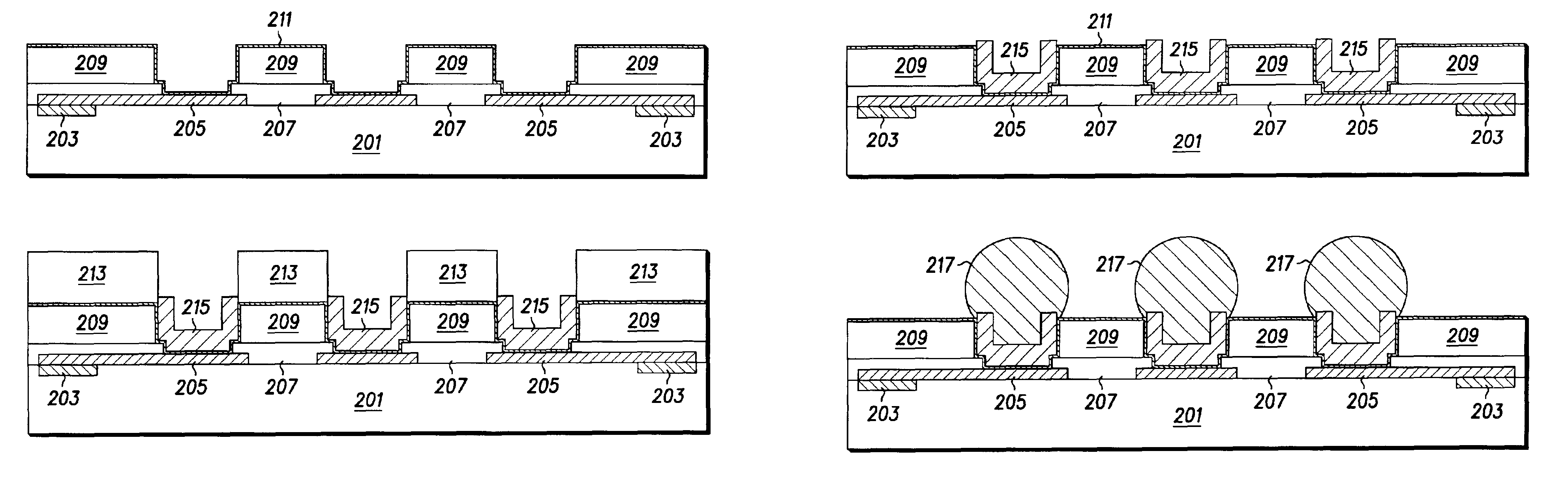
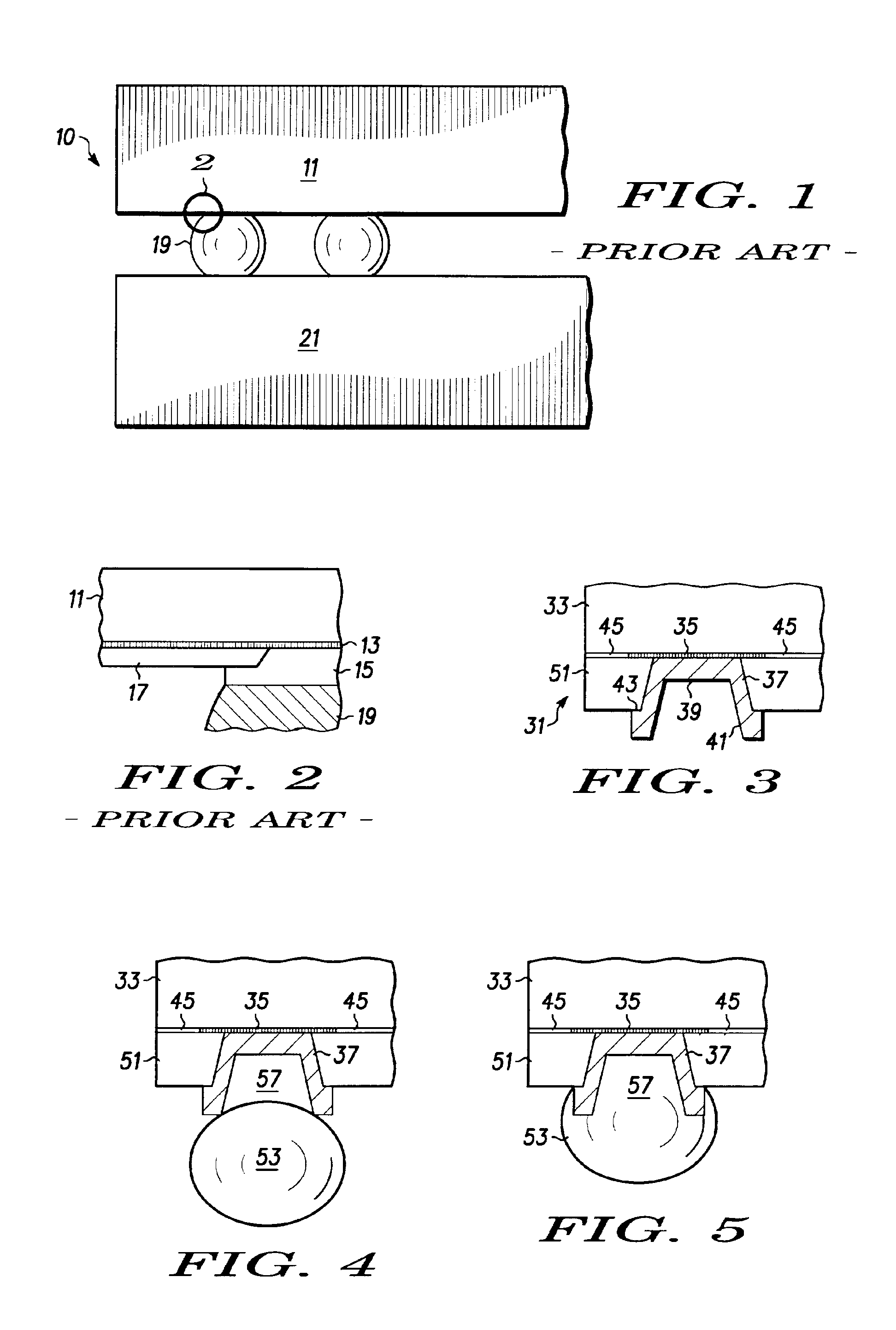
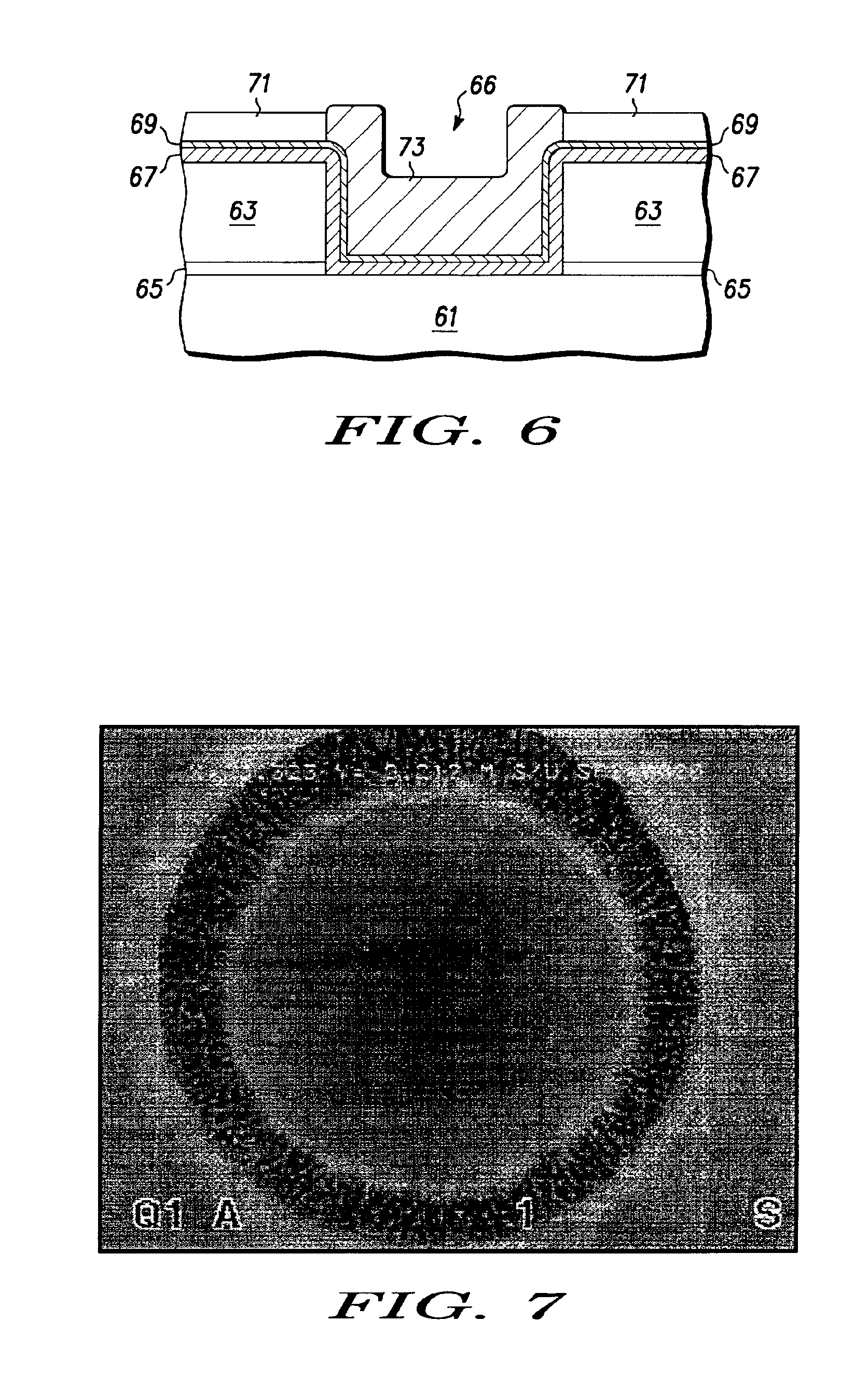
To date, however, relatively little consideration has been given to the development of UBM structures that promote solder joint reliability.
Also, little thought has been given to

Method used


Image

  • Under bump metallurgy structural design for high reliability bumped packages
  • Under bump metallurgy structural design for high reliability bumped packages
  • Under bump metallurgy structural design for high reliability bumped packages

Examples


example 1

[0058]This example illustrates the increase in lifetime and strain distribution afforded by solder joints made in accordance with the teachings herein.

[0059]The virtues of a variety of solder joints and UBM designs were explored by subjecting the designs to a finite element analysis using a 2-D plane strain approach. This type of analysis is described in detail in O. C. Zienkiewicz, “The Finite Element Method” (3rd Ed. 1977). Other, more elaborate and time intensive analyses can also be performed for this purpose, and some of these analyses can afford somewhat greater accuracy in certain situations. These include, for example, 3-D non-linear finite element methods. However, the use of a 2-D plane strain non-linear finite element approach here greatly simplifies the model while providing decent comparative results.

[0060]The designs were also studied using a global model-sub-model approach, which enables the evaluation of the detailed stress distribution in the under bump metallurgy a...


PUM


Abstract

A method for creating an under bump metallization layer (37) is provided. In accordance with the method, a die (33) is provided which has a die pad (35) disposed thereon. A photo-definable polymer (51 or 71) is deposited on the die pad, and an aperture (66) is created in the photo-definable polymer. Finally, an under bump metallization layer (37) is deposited in the aperture. A die package is also provided comprising a die having a die pad (35) disposed thereon, and having an under bump metallization layer (37) disposed on the die pad. The structure has a depression or receptacle (57) therein and has a thickness of at least about 20 microns.

Description

FIELD OF THE INVENTION[0001]The present invention relates generally to the formation of solder joints, and more particularly to under bump metallurgy structural designs, and their methods of production, which can be used to improve the integrity of solder joints.BACKGROUND OF THE INVENTION[0002]The use of solder bumps in attaching die to flip-chip packaging is well known in the art. FIG. 1 and FIG. 2 (the later of which is a magnified view of REGION 2 of FIG. 1) illustrate one prior art configuration 10 that can be used for this purpose. As shown therein, a die 11 is provided which has an I / O pad or die pad 13 disposed thereon. A photo polymer passivation layer 17 is provided to protect the die from damage during processing. An Under Bump Metallurgy (UBM) structure 15 is disposed on the die pad, and a solder ball 19 is placed or formed on top of the UBM structure. The solder ball is used to form an electrical and mechanical connection between the die and a Printed Circuit Board (PCB...

Claims


Application Information

Patent Timeline
IPC IPC(8): H01L21/02H01L21/60H01L21/288H01L23/485H01L23/48
CPCH01L21/2885H01L24/13H01L24/05H01L24/11H01L24/03H01L2224/0401H01L2224/05558H01L2224/05599H01L2224/11901H01L2224/13022H01L2224/131H01L2224/16H01L2924/01005H01L2924/01006H01L2924/01013H01L2924/01014H01L2924/01015H01L2924/01022H01L2924/01028H01L2924/01029H01L2924/01039H01L2924/01047H01L2924/01049H01L2924/0105H01L2924/01051H01L2924/01078H01L2924/01079H01L2924/01082H01L2924/01322H01L2924/014H01L2924/05042H01L2924/14H01L2224/11334H01L2224/1132H01L2224/13023H01L2924/00013H01L2924/01023H01L2924/01024H01L2924/01033H01L2224/13006H01L2224/05572H01L2924/0002H01L2224/05647H01L2224/0347H01L2924/00014H01L2224/03462H01L2224/13099H01L2924/00012H01L2224/05552H01L2224/023H01L2924/0001
Inventor SARIHAN, VIJAYFAY, OWENKESER, LIZABETH ANN
Owner NXP USA INC
Why Eureka
Try Eureka