Method for reducing the influence of a DC current component in the load current of an asynchronous motor

a technology of asynchronous motors and components, applied in the direction of motor/generator/converter stoppers, dynamo-electric converter control, dynamo-electric gear control, etc., can solve the problems of hard or completely impossible soft start of motors, and achieve uniform rise and profile

Inactive Publication Date: 2005-08-16
SIEMENS AG
View PDF23 Cites 22 Cited by
  • Summary
  • Abstract
  • Description
  • Claims
  • Application Information

AI Technical Summary

Benefits of technology

[0007]An embodiment of the invention is based on the knowledge that, by virtue of their principle of operation, when phase gating takes place in the range of 75°±10° in two-phase three-phase controllers, these controllers have a tendency to produce asymmetric current half-cycles of positive and negative polarity. In consequence, the successive positive and negative current half-cycles which alternate with one another each have a different time duration and amplitude. This leads to a DC component in the load current which, for example in the case of asynchronous machines, produces braking torques and thus makes it harder or completely impossible to start them softly.
[0008]Thus the phase-gated load current, which has current half-cycles of alternate polarity and of a different duration and amplitude, and accordingly DC components which produce braking torques, can be influenced such that the DC components are reduced without using measurement devices to determine the current / time integrals which are enclosed by the current half-cycles, thus ensuring that all the effective currents have a uniform rise and profile in order to achieve the desired soft starting.

Problems solved by technology

This leads to a DC component in the load current which, for example in the case of asynchronous machines, produces braking torques and thus makes it harder or completely impossible to start them softly.

Method used


Image

  • Method for reducing the influence of a DC current component in the load current of an asynchronous motor
  • Method for reducing the influence of a DC current component in the load current of an asynchronous motor
  • Method for reducing the influence of a DC current component in the load current of an asynchronous motor

Examples


Embodiment Construction

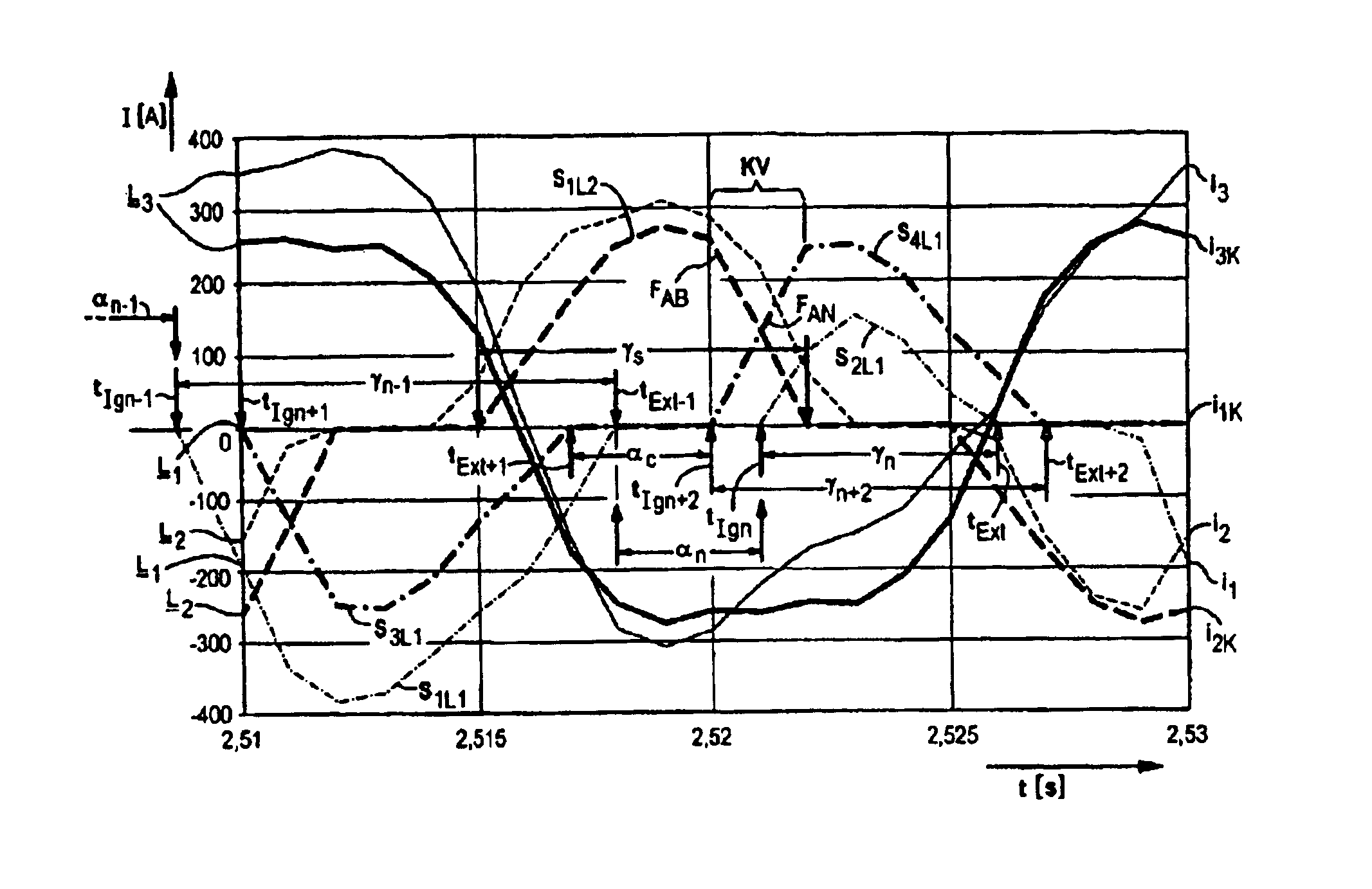
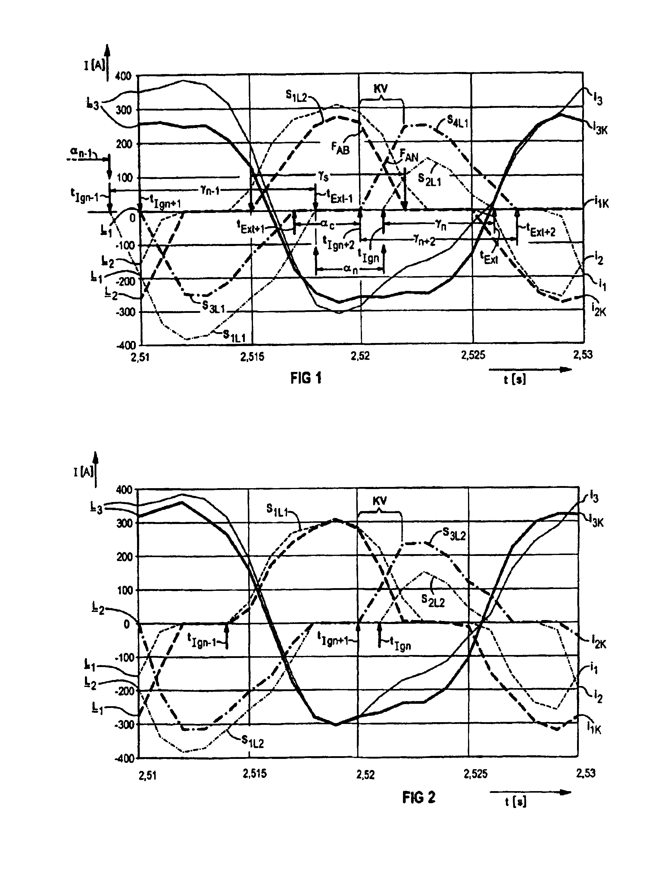
[0014]FIG. 1 uses a diagram to show the time profile of a three-phase current during starting of an asynchronous machine using a two-phase three-phase controller, before and after the use of a first method for reducing the influence of a DC component. This illustration shows a current i1 and i2 in a first and a second controlled phase L1 and L2, respectively, as well as a current i3 in a third, uncontrolled phase L3, in each case having pronounced DC components.

[0015]Furthermore, the currents i1 and i2 have a respectively associated current i1K and i2K corrected according to the method, and the current i3 has an associated current i3K, which is influenced by the correction according to the method, all in phase. In order to control the phases L1 to L3, the phase gating is supplied by a function that can be determined via a ramp, in particular a linear ramp.

[0016]The first method for reducing the influence of the DC component provides that, first of all, the current flow angle γn−1 in...


PUM


Abstract

A method with which the load current and thus the load moment of an asynchronous motor that is controlled via a phase-controlled two-phase thyristor power controller, can be easily influenced so as to allow a smooth starting operation. According to a first embodiment, the ignition point is determined in the controlled phase in order to adapt the flow angles of the subsequent current half waves. According to a second embodiment, the ignition point of the subsequent current half waves is brought forward in both controlled phases.

Description

[0001]This application is the national phase under 35 U.S.C. §371 of PCT International Application No. PCT / DE02 / 04091 which has an International filing date of Nov. 4, 2002, which designated the United States of America and which claims priority on German Patent Application number DE 101 56 216.0 filed Nov. 15, 2001, the entire contents of which are hereby incorporated herein by reference.FIELD OF THE INVENTION[0002]The present invention is generally directed to a method for reducing the influence of a DC component in the load current of an asynchronous motor.BACKGROUND OF THE INVENTION[0003]Three-phase controllers use a principle of phase gating to control the amount of energy supplied to an electrical load. This allows the starting currents and torques in asynchronous machines to be reduced. The phase gating angle is used as a measure of the amount of energy supplied. Current half-cycles of alternate polarity flow through the load which is connected to the output of the three-phas...

Claims


Application Information

Patent Timeline
Patent Type & Authority Patents(United States)
IPC IPC(8): H02P25/02H02P25/14
CPCH02P1/28
Inventor FRITSCH, ANDREASGRIEPENTROG, GERDRUNGGALDIER, DIETHARDSEITZ, JOHANN
Owner SIEMENS AG
Why Eureka
Try Eureka