Flexible multi-layered probe for measuring a signal from an object

Inactive Publication Date: 2005-08-16
NAT CHUNG SHAN INST SCI & TECH
View PDF13 Cites 9 Cited by
  • Summary
  • Abstract
  • Description
  • Claims
  • Application Information

AI Technical Summary

Benefits of technology

[0009]The invention provides a flexible probe. A flexible high-frequency substrate and a claw-shape probe tip that extends beyond the substrate are incorporated to

Problems solved by technology

Further, only a limited range of pressure can be applied to the probe while touching the object, for avoiding damaging the probe.
However, because only the claw-shaped probe tip has flexibility, the to

Method used


Image

  • Flexible multi-layered probe for measuring a signal from an object
  • Flexible multi-layered probe for measuring a signal from an object
  • Flexible multi-layered probe for measuring a signal from an object

Examples


Embodiment Construction

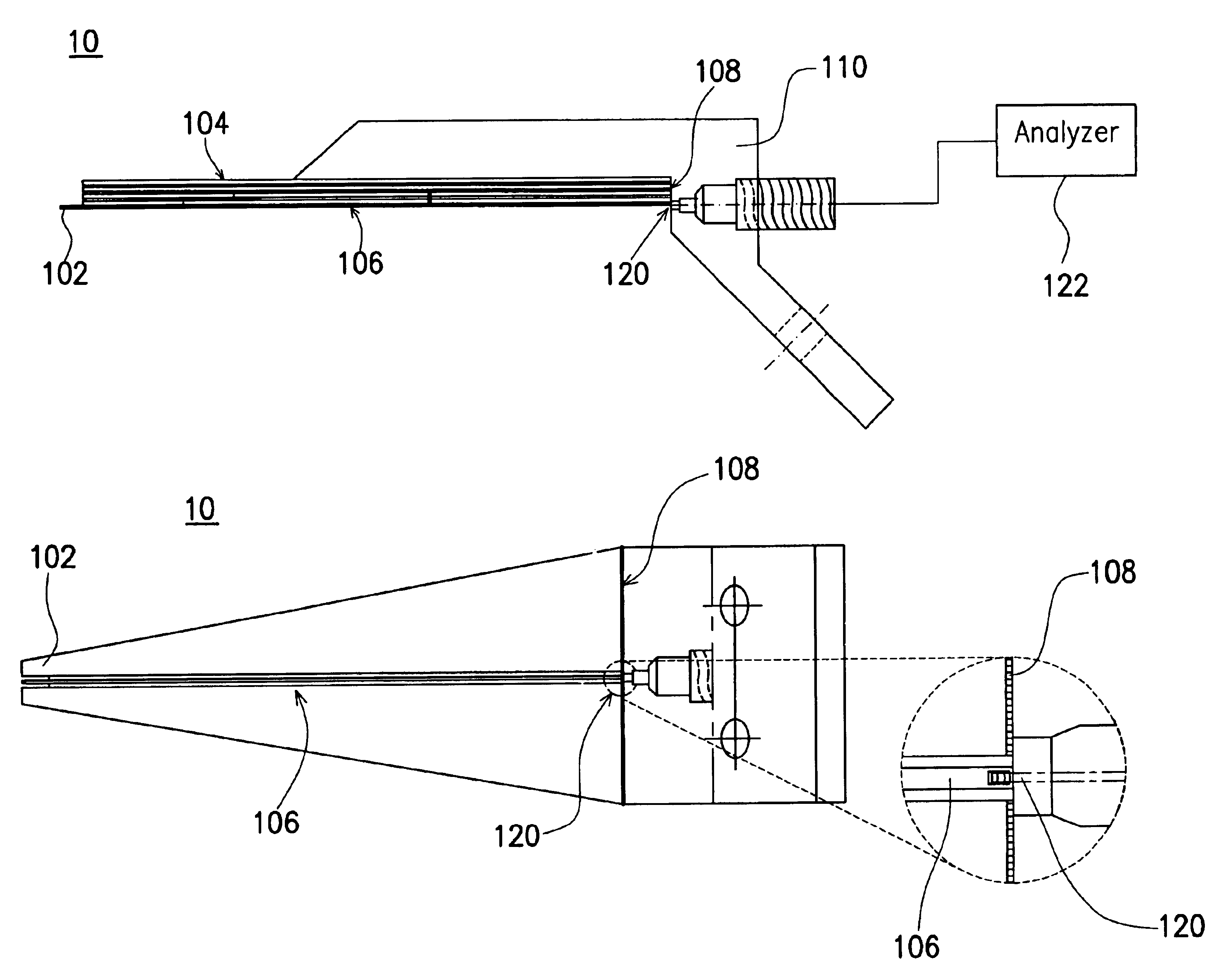
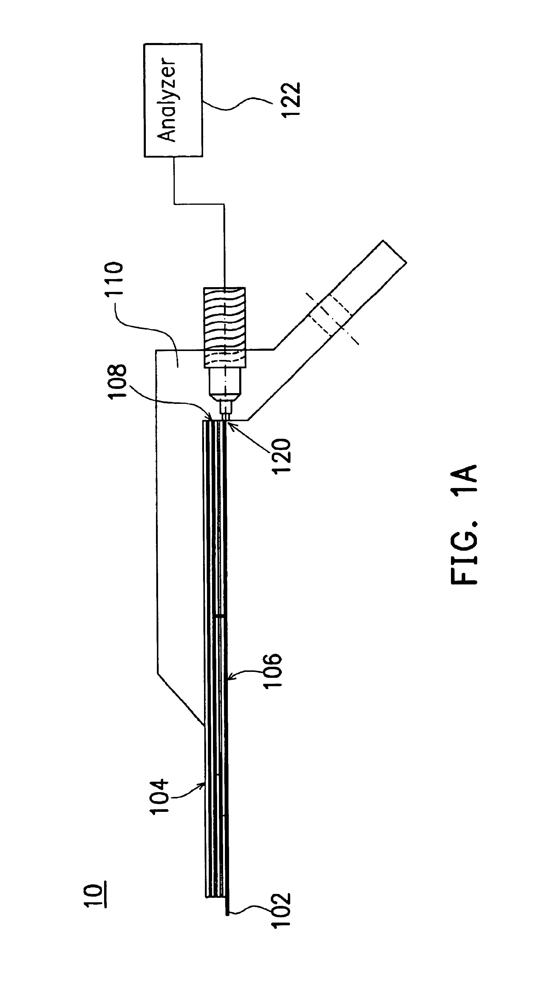
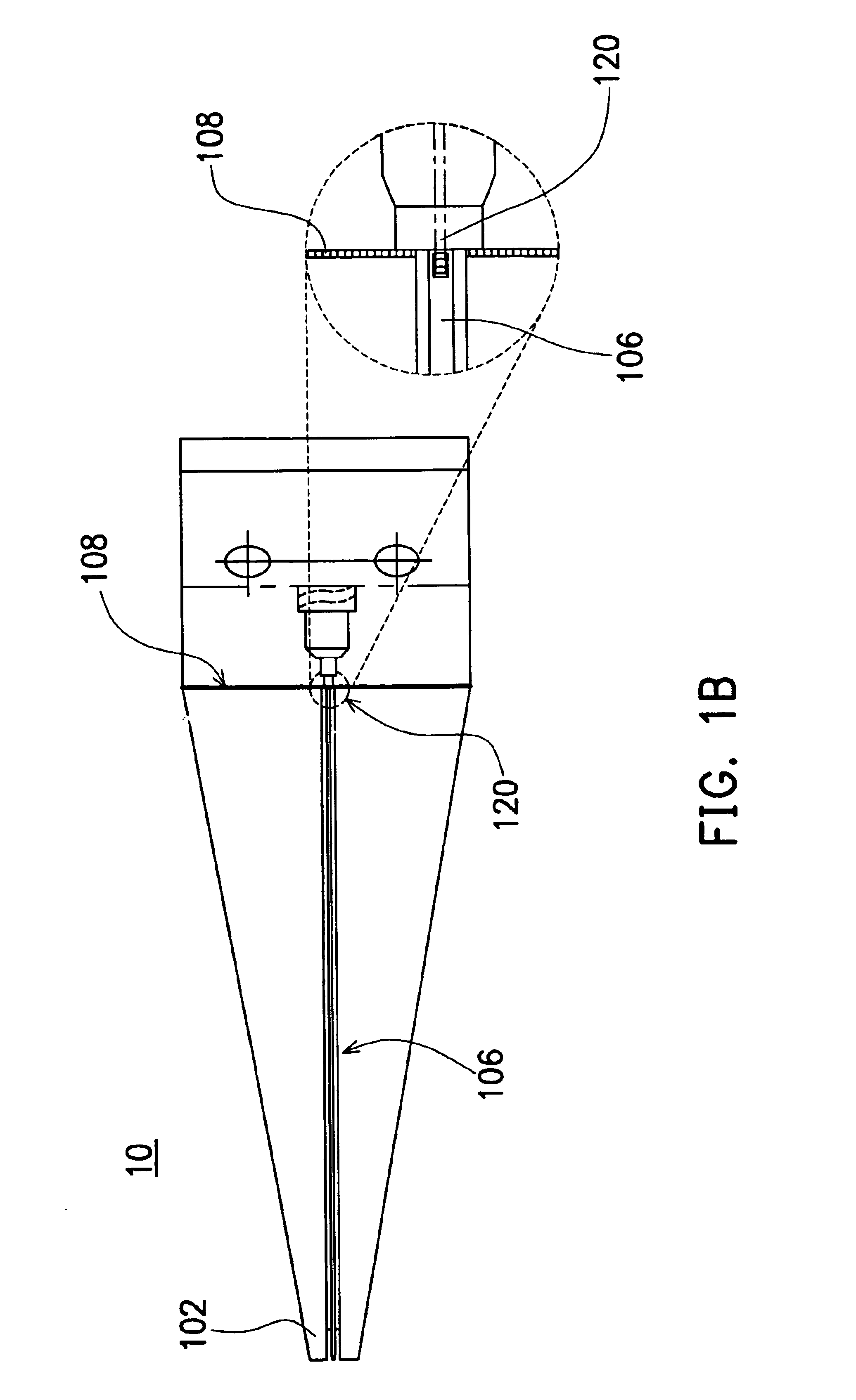
[0027]Referring to FIGS. 1A-1B, the structure of a flexible probe according to one preferred embodiment of the present invention is shown. The probe 10 can be used to measure the signals, for example, microwave signals, on wafer or in the board level measurement. In FIG. 1A, the probe 10 includes a probe tip 102, a flexible multi-layered dielectric substrate 104, a planar transmission structure 106, and a fixed end 108 for supporting the probe 10. The probe tip 102 is connected to the planar transmission structure 106, while the planar transmission structure 106 is attached to a surface of the dielectric substrate 104 and supported by the dielectric substrate 104. Preferably, the probe tip is made of a metal material and has a claw shape. The probe tip 102 extends outward and outthrusts from the planar transmission structure into the surrounding air. That is, the probe tip 102 is not in direct contact with the dielectric substrate 104. The probe tip 102 can move up and down and rota...


PUM


Abstract

A flexible probe, applicable for measuring signals from the object with an uneven surface, includes at least a probe tip, a flexible multi-layered dielectric substrate, a planar transmission structure and a coaxial transmission structure. The probe tip is connected to the planar transmission structure and extends beyond the flexible dielectric substrate. The planar transmission structure is attached to and supported by the flexible dielectric substrate and then connected to the coaxial transmission structure.

Description

CROSS-REFERENCE TO RELATED APPLICATION[0001]This application is a continuation-in-part of prior application Ser. No. 10 / 033,749, filed on Dec. 19, 2001 now U.S. Pat. No. 6,759,859.BACKGROUND OF THE INVENTION[0002]1. Field of the Invention[0003]The invention relates in general to a probe, and more particularly, to a flexible probe used to measure microwave and high-speed signals from an uneven surface.[0004]2. Description of the Related Art[0005]In addition to the printed circuit board (PCB), the versatile applications of microwave and high-speed signal circuit further include the hybrid circuit, the multi-chip module (MCM), and the integrated circuit (IC). For the microwave circuit and the high-speed signal circuit, the most accurate and convenient measurement methods include on-wafer measurement. To obtain an accurate measurement result, a good probe is required.[0006]The technique of probe used for on-wafer measurement has been disclosed in U.S. Pat. No. 4,697,143 in September 198...

Claims


Application Information

Patent Timeline
IPC IPC(8): G01R1/067G01R1/073
CPCG01R1/06772G01R1/07357
Inventor DENG, JOSEPH D. S.LEE, HONG-CHYI
Owner NAT CHUNG SHAN INST SCI & TECH
Why Eureka
Try Eureka