Terminating resistor driver for high speed data communication

a resistor driver and data communication technology, applied in logic circuit coupling/interface arrangement, pulse technique, baseband system details, etc., can solve the problems of increasing the power dissipation of the driver, increasing and reducing the maximum signal amplitud

Inactive Publication Date: 2005-08-16
MARVELL ASIA PTE LTD
View PDF14 Cites 17 Cited by
  • Summary
  • Abstract
  • Description
  • Claims
  • Application Information

AI Technical Summary

Benefits of technology

[0007]In view of the foregoing and other problems, disadvantages, and drawbacks of the conventional driver circuits the present invention has been devised, and it is an object of the present invention to provide a structure and method for an improved driver circuit having resistors in parallel to control impedance and signal amplitude.
[0008]In order to attain the object(s) suggested above, there is provided, according to one aspect of the invention a driver circuit having a plurality of parallel resistors, where a total impedance of all the resistors equals an impedance of an associated transmission line. The invention includes a switch that is ...

Problems solved by technology

This voltage overhead increases the driver's power dissipation and decreases the maximum signal amplitude.
The additional voltage needed for proper operation of the current sources (V101(min)) and switches (V102) results in increased power dissipation and limits the maximum output signal for any given VH and VL.
The difference between the output range of the amplifier (VAMP(max)−VAMP(mi...

Method used


Image

  • Terminating resistor driver for high speed data communication
  • Terminating resistor driver for high speed data communication
  • Terminating resistor driver for high speed data communication

Examples


Embodiment Construction

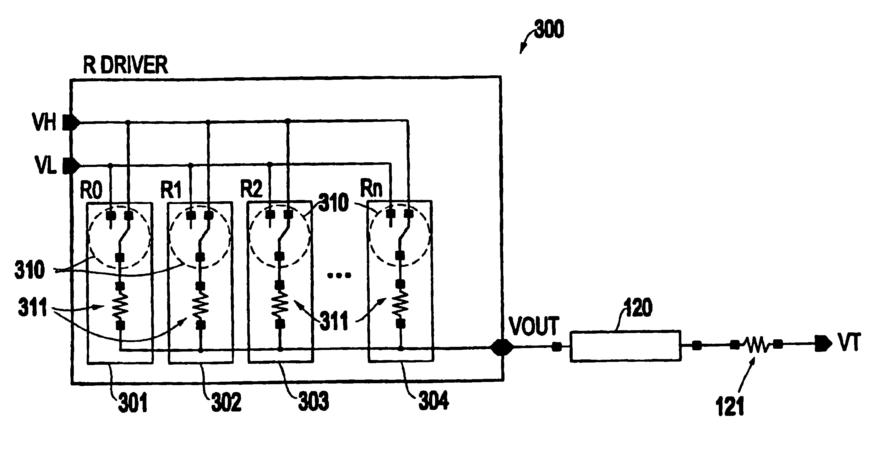
[0020]As mentioned above, there is a need to provide a driver circuit that has a specific impedance matching the impedance of the transmission line, that neither consumes large quantities of power nor decreases maximum signal amplitude. The invention overcomes the conventional problems and provides a driver that matches the necessary impedance with minimum power dissipation and maximum signal amplitude by utilizing a number of resistors in parallel. More specifically, FIG. 3 illustrates one embodiment of the invention.

[0021]In FIG. 3, the driver circuit 300 and the resistor switch segments are shown as items 301-304. Each switch segment 301-304 includes a switch 310 and a resistor 311. The switches 310 switch between VH and VL and pass the signal through the resistor 311. While there are a limited number of resistive elements shown in the drawings, one ordinarily skilled in the art would understand that the number of resistive elements is not limited and depend upon the specific des...


PUM


Abstract

A method and structure for a driver circuit having a plurality of parallel resistors, where a total impedance of all the resistors equals an impedance of an associated transmission line and a switch adapted to combine the resistors to control an output level of the driver. The driver circuit's switch selectively connects the resistors to either a voltage high signal or a voltage low signal. The first set of the switches connect a voltage high signal to a first resistor of the resistors and a second set of switches connect a voltage low signal to a second resistor of the resistors. The switch has a matched pair of opposite type transistors. The driver circuit has balancing resistors connected to the switch, the balancing resistors are sized to balance the resistance within the driver circuit. The resistors are the balancing resistors and the drivers are connected to the switches.

Description

BACKGROUND OF INVENTION[0001]1. Field of the Invention[0002]The present invention generally relates to high speed data communication between digital circuits that require the driver (and / or receiver) circuits be terminated with an impedance that matches the characteristic impedance of the transmission path linking the transmitter and receiver. The present invention discloses a resistor based driver that maintains a constant output impedance while allowing the control circuits to switch the output drive to the desired level.[0003]2. Description of the Related Art[0004]Existing drivers use current sources or voltage amplifiers (which require a certain amount of voltage overhead) to insure that the driver remains in the linear operating region of the current source or voltage amplifier. This voltage overhead increases the driver's power dissipation and decreases the maximum signal amplitude.[0005]For example, FIGS. 1 and 2 represent conventional driver circuits that utilize current sou...

Claims


Application Information

Patent Timeline
IPC IPC(8): H03K19/00H04L25/02
CPCH03K19/0005H04L25/0278H04L25/028H04L25/0282H04L25/0292
Inventor CRANFORD, JR., HAYDEN C.LUNDBERG, MARTIN B.
Owner MARVELL ASIA PTE LTD
Why Eureka
Try Eureka